
Do you enjoy the content ? DONATE with PayPal to support me !
Get $5 of NEW USER FREE CREDIT using PCBWay. Full feature custom PCB prototype services, PCB assembly, SMD stencils, CNC / 3D Printing.
Introduction
Simple direct conversion receiver with MC3361 and LM386 for the 80m band. Based on the Lidia direct conversion receiver. A present from Andrei – YO6TJJ. This receiver kit was developed by roWaves. Sadly the kit it’s no longer available for sale.
A version of this article was also published in the RADIO Magazine ( No. 2 October 2023 ), available in digital format translated in English downloadable as a PDF file.
There are many people who would like to make their first steps in amateur radio. Generally they don’t have a receiver to listen to CW or SSB signals and get used to radio traffic and the language used by amateur radio operators. A receiver that’s already built can be expensive compared to what I will present to you in this article. This receiver was based on the Lidia Direct Conversion Receiver developed by Wlodzimierz Salwa – SP5DDJ. I received the kit from Andrei – YO6TJJ to test it. It was the first direct conversion receiver that I built.
The Schematic
The receiver works between 3.5MHz and 3.8MHz ( 80m amateur radio band ). As you can tell from the schematic, the main element it’s the MC3361 integrated circuit. LM386 was used as audio amplifier. The signal from the antenna passes through the POT1 potentiometer. This one acts as an RF attenuator, adjusting the sensitivity of the receiver. Then it passes through the band-pass filter, to the receiver. The filter, made using L1, L2 and capacitors C2, C3, C4, C5 and C6, it’s important and necessary to select the 80m band. The VFO operates in the circuit using the inductor L3, the varactor D1 and the multiturn potentiometer POT2.
After turning on the device, the frequency may deviate slightly for 15 – 20 minutes until the VFO stabilizes thermally. The MC3361 integrated circuit also includes an active audio filter, with the external components: R3, R4, R5, C16, C17 and the SW1 switch. You can switch between the CW or the SSB filter. The audio amplifier was made with the LM386 integrated circuit. The volume is adjusted using the potentiometer POT3. The audio output works both with headphones or an 8 Ohm speaker. Towards the end of the article I will give you some tips for good audio quality.

Direct Conversion Receiver With MC3361 Schematic
Building The Receiver
The receiver can be built using different methods. Obviously the easiest way is to use a PCB board like the one in the kit. You can also build it Manhattan style. It’s important to make the connections between the components as short as possible. Another important aspect is the use of quality components. No matter if they are new or recovered from old circuits, I always measure them. In this article I will focus on using the PCB board that came with the kit. Since the kit it’s no longer available, when I will have a little free time I will design a single layer PCB board that you can order from PCB Way, or you can make them at home using the toner transfer method.
You could install the components in a certain order. This way you can check the stages of the circuit one by one. I always start with the power supply and the audio amplifier. Then I power the receiver and check if it works. The next step would be the bandpass filter. If you use a nanoVNA to adjust the filter, it’s a lot easier to do it at this stage. I think the most correct way of building it is the one in which you feel the most comfortable and confident.
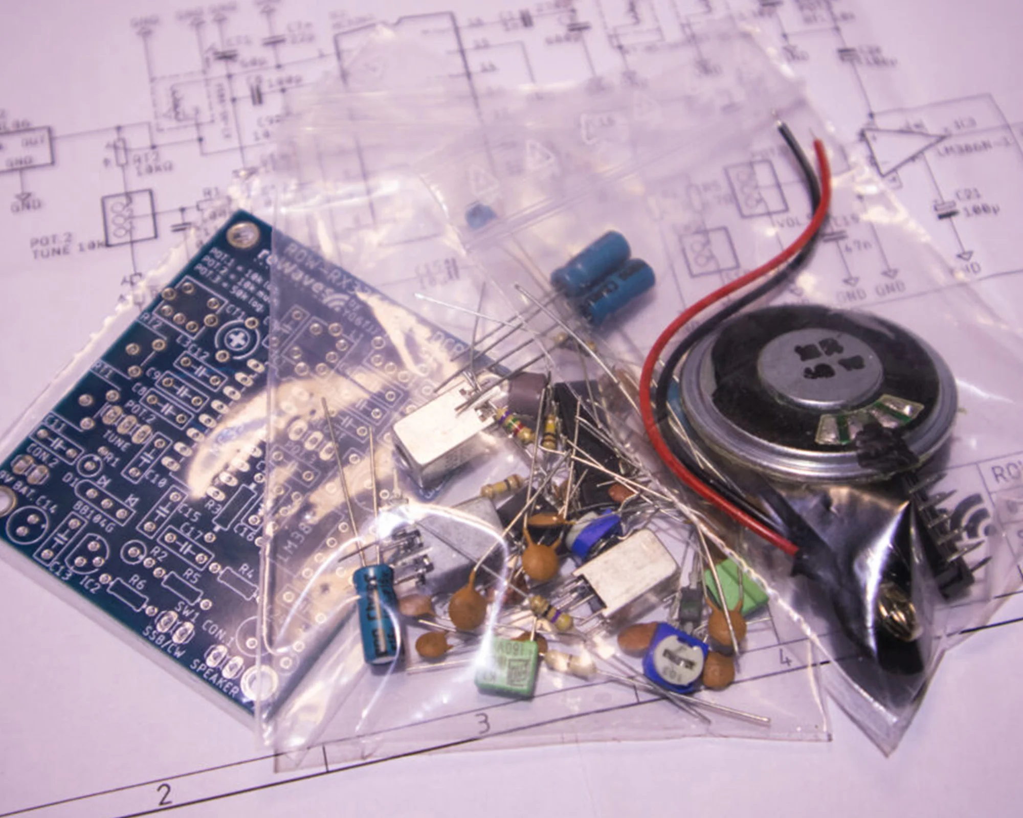
Direct Conversion Receiver Kit With MC3361
You will also need an enclosure. I prefer an aluminum one because it’s more resistant and it will protect the circuit from possible interferences. Whether we are talking about this receiver or any other circuit, patience and attention will always ensure you good results. Finish installing the external components and then make the necessary adjustments for the best sensitivity and performance. This receiver can be built quite easily in just a few hours. In the image down bellow you have the completed receiver with all the components ( except the external ones ).

Direct Conversion Receiver With MC3361
Modifications To The Inductors
The original Lidia receiver used three 10uH inductors. The inductors used in the kit are variable inductors: 8-18μH | Mitsumi | 52199-33331. The inductors also contain a 120pF capacitor in parallel with the coil. This must be removed as it’s not needed, but do it very carefully ( with a cutter ), not to cut the coil wire. This PCB was specifically designed to use these inductors which are very easy to adjust. See details in the images bellow. I will use similar inductors when I will design the PCB board since it’s easy to adjust the bandpass filter and the VFO.
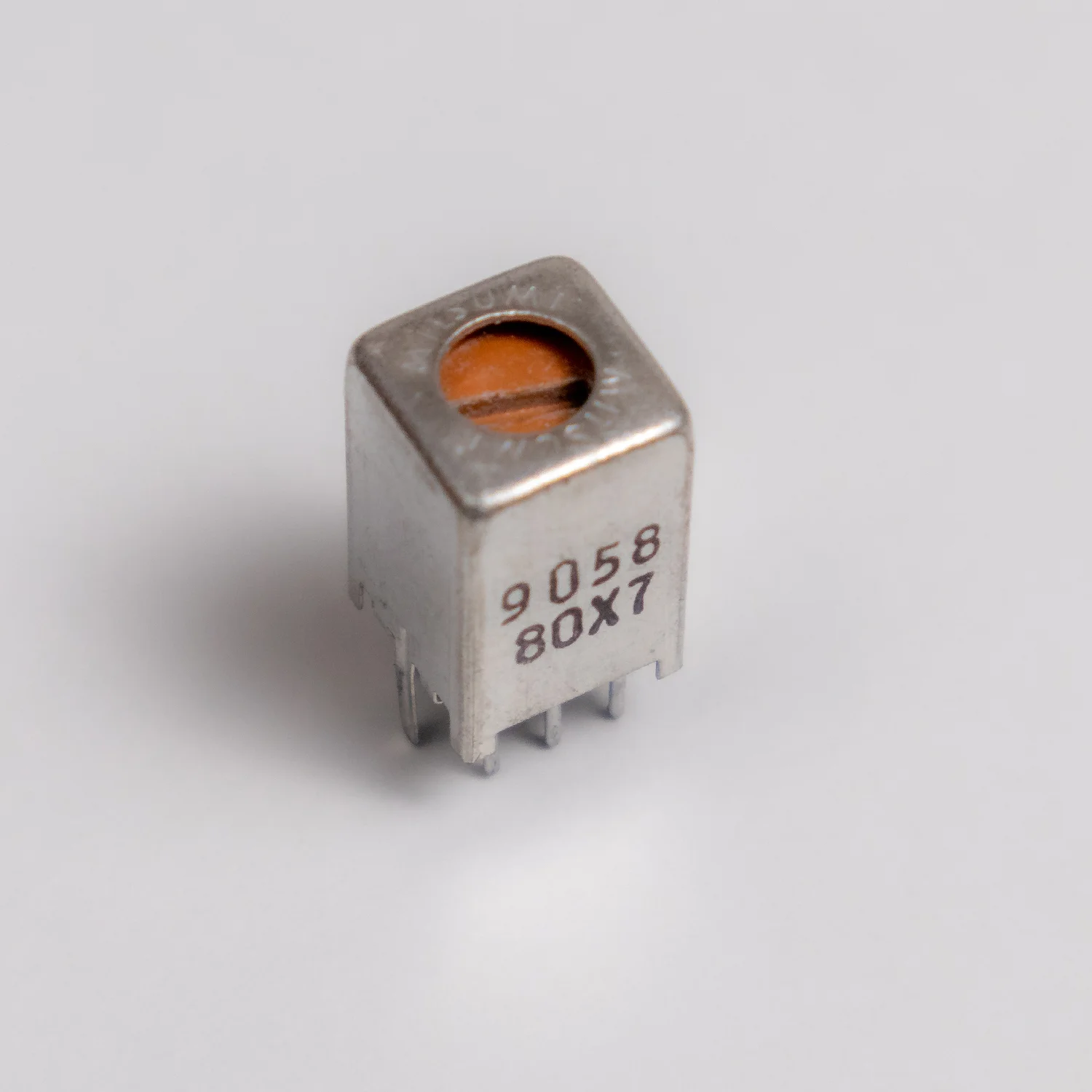
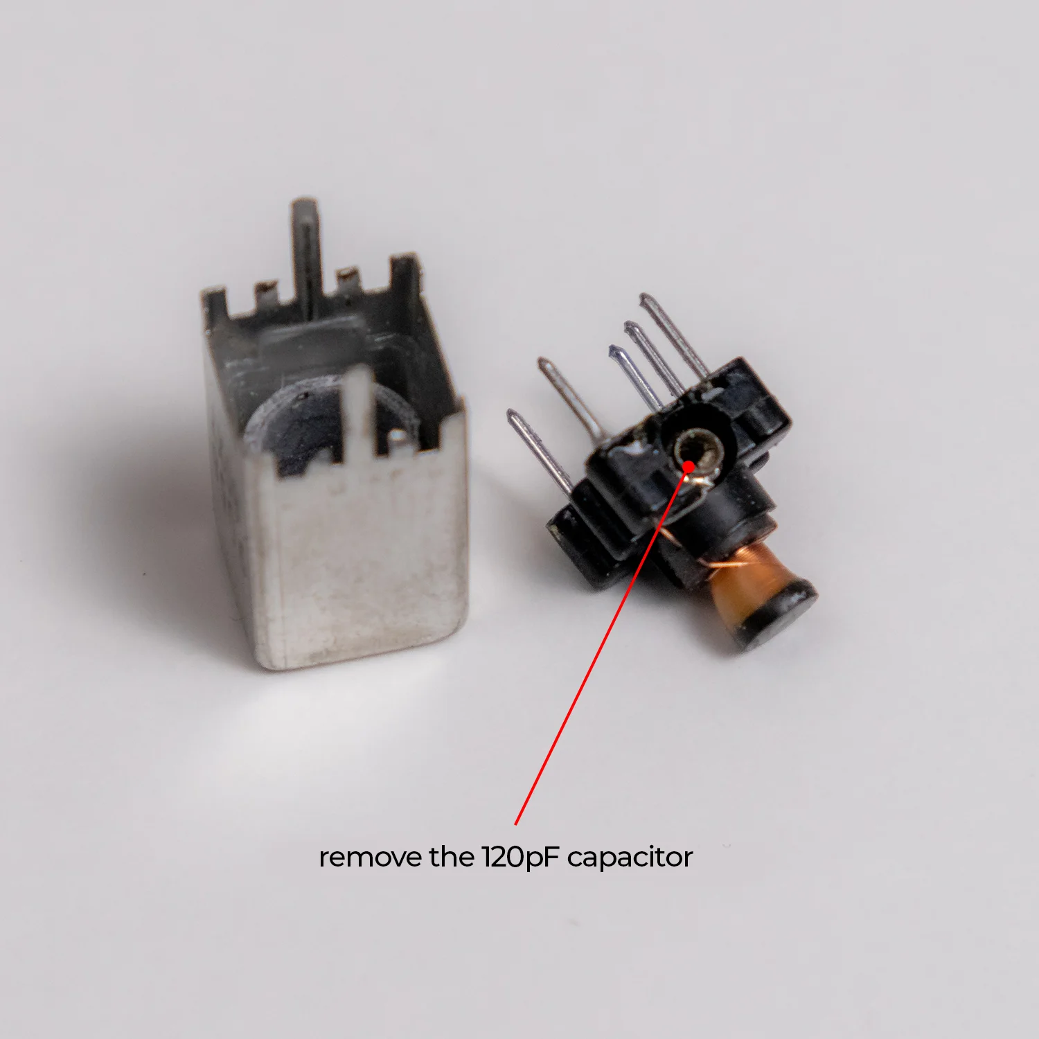
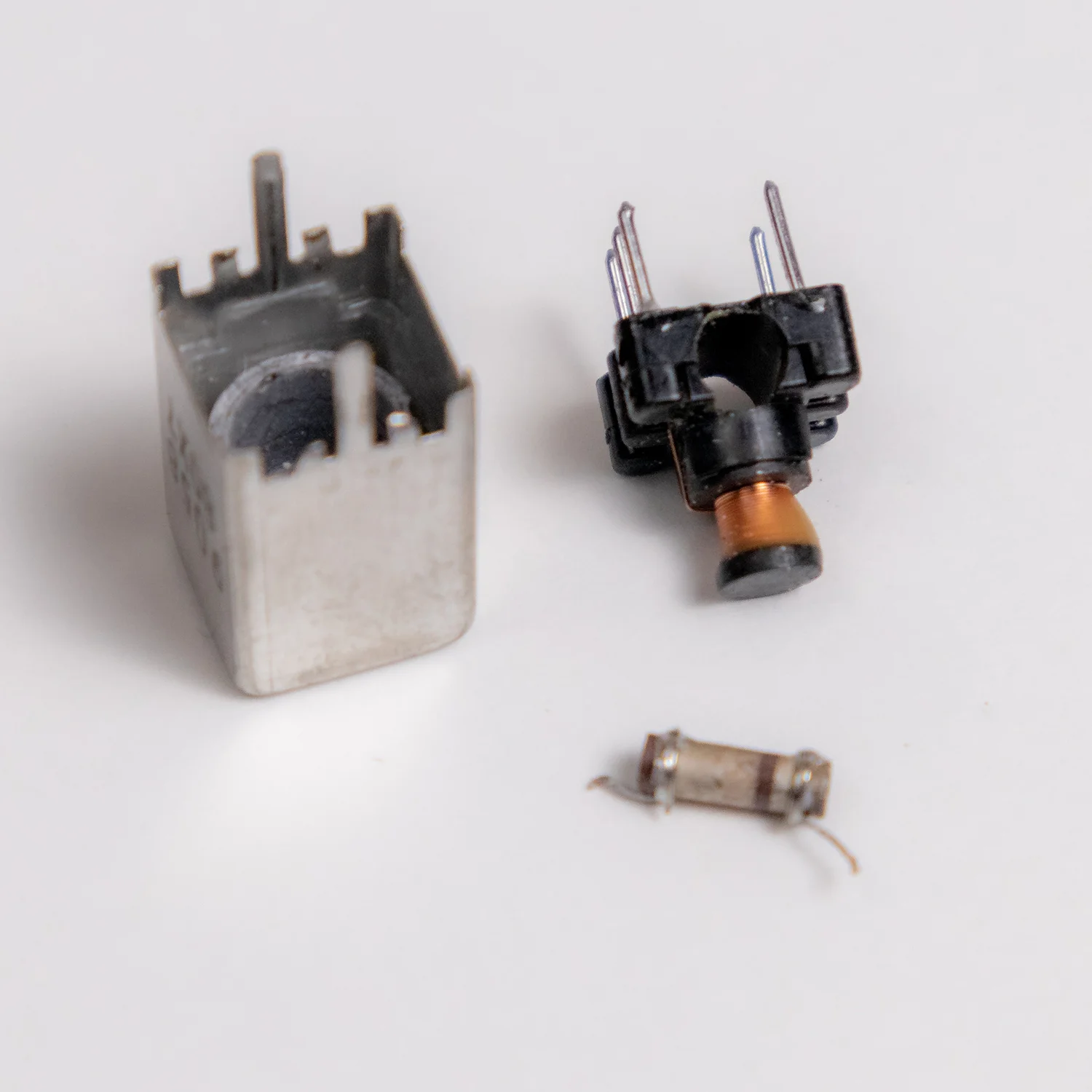
8-18μH | Mitsumi | 52199-33331
Adjustments and Testing
Generally beginners do not have the necessary equipment for adjustments. So I will try to explain these steps as simply as possible to help you adjust the receiver without measuring devices. Start by powering the receiver and checking whether it works or not. The next step is to check the audio amplifier by adjusting the POT3 potentiometer. Touch pin 2 of the LM386 integrated circuit with a screwdriver or tweezers and a specific noise will be heard in the speaker. If everything is OK, move on to the demodulator part.
Gently turn the multi-turn potentiometer POT2 and you should be able to tell quite easily if the VFO works correctly. Do this with the receiver connected to a dedicated antenna or a well-extended wire used as an antenna obviously. Checking if the VFO work or not will be quite obvious because you can hear the changes in the received frequency in the speaker. Now let’s adjust the receiver so it will receive frequencies between 3.5MHz and 3.8MHz. Here we have a few options available:
- The easiest is to use a frequency meter ( optional in the receiver construction );
- The second option is to use a transmitter for the 80m band;
- Another option is to use an online SDR receiver. In Romania we have several options available and I recommend using one as close as possible to your QTH ( location ).
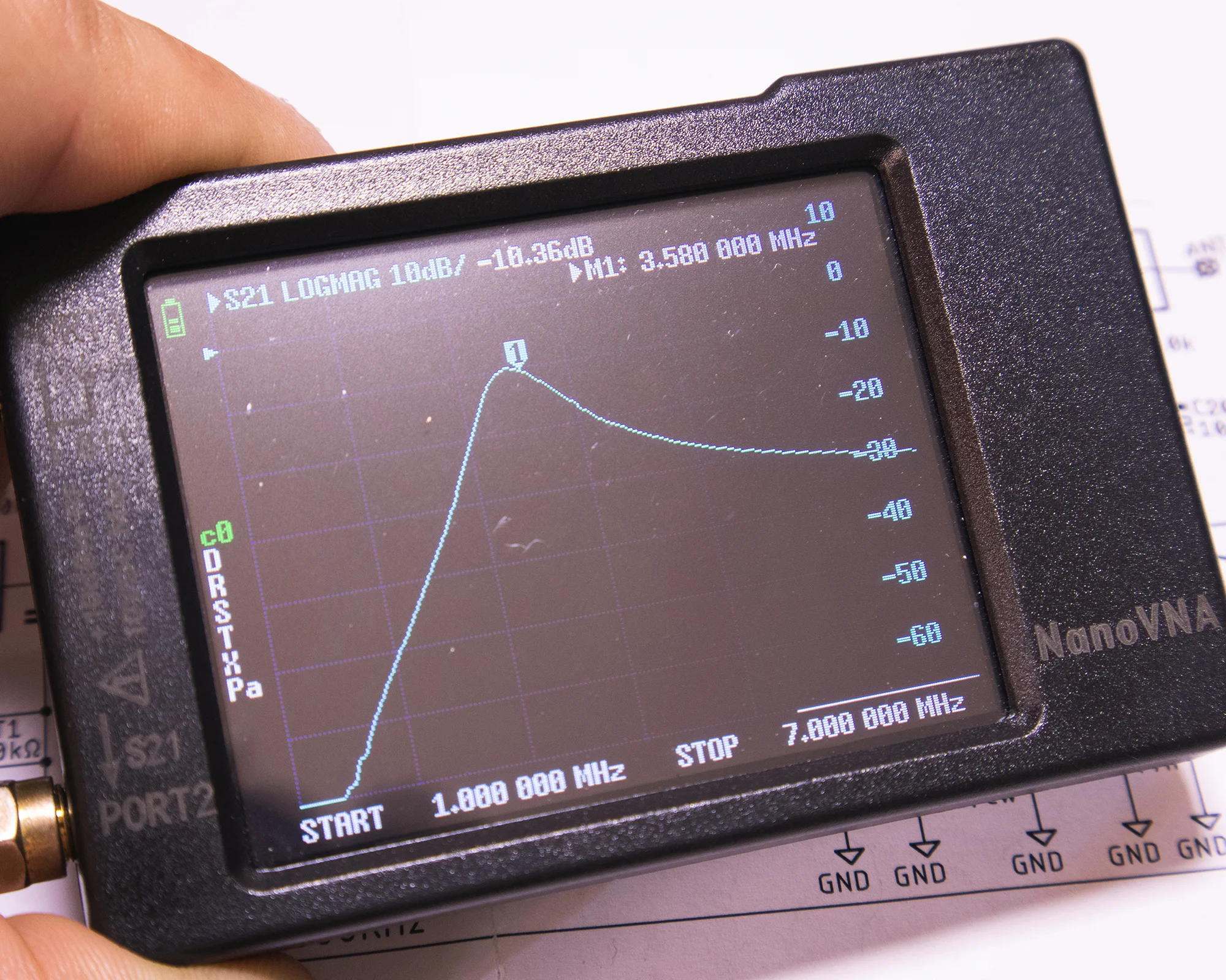
Bandpass Filter Test – 80m Band
Listen to the 3.5MHz frequency on the SDR ( or somewhere around 3.5MHz where there are signals ). Turn the multi-turn potentiometer to the left all the way. Using a plastic screwdriver, turn the ferrite core of the adjustable inductance L3 until you receive the same signal as on the SDR. Now turn the potentiometer to the right all the way and also move the SDR to 3.8MHz. Check if you have the same signal in the receiver is you hear on the SDR.
The receiver can also receive signals below 3.5MHz or above 3.8MHz. To make the final adjustment so that the receiver it’s exactly between 3.5MHz and 3.8Mhz, use RT1 and RT2 ( trimmer resistors ). With these you can adjust the minimum and maximum of the received frequencies. After the adjustment, the band-pass filter follows. Using the same plastic screwdriver and the receiver back on 3.5MHz, rotate the ferrite cores of L1 and L2 until the received signal has maximum strength. Repeat the same procedure with the receiver tuned on 3.8MHz. Then make sure that the frequencies between 3.5MHz and 3.8MHz have the same strength.
Frequency Counter
I don’t really like adjusting the receiver using the SDR method. It’s time consuming, especially if you have to wait for good propagation conditions. For that reason I decided to also install the frequency counter I had from Nigel – ZL1NAY. The frequency counter needed a preamplifier in order to work with this receiver. Down bellow you have the simple schematic I used.
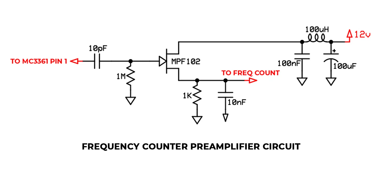
Frequency Counter Preamplifier Schematic
Here you have two more images with the frequency counter I used. Also with the homebrew version of the preamplifier installed on the back of the frequency counter. This type of frequency counter can be found on AliExpress most of the time at reasonable prices. Some are good, others have questionable quality and performance. So I guess be careful and don’t always pick the cheapest one. I was lucky and the one I have works spot on. Power the frequency counter from the same pins where you connect the power supply to the receiver. Then connect the output of the preamplifier to pin 1 of the MC3361 integrated circuit as shown in the schematic of the preamplifier.
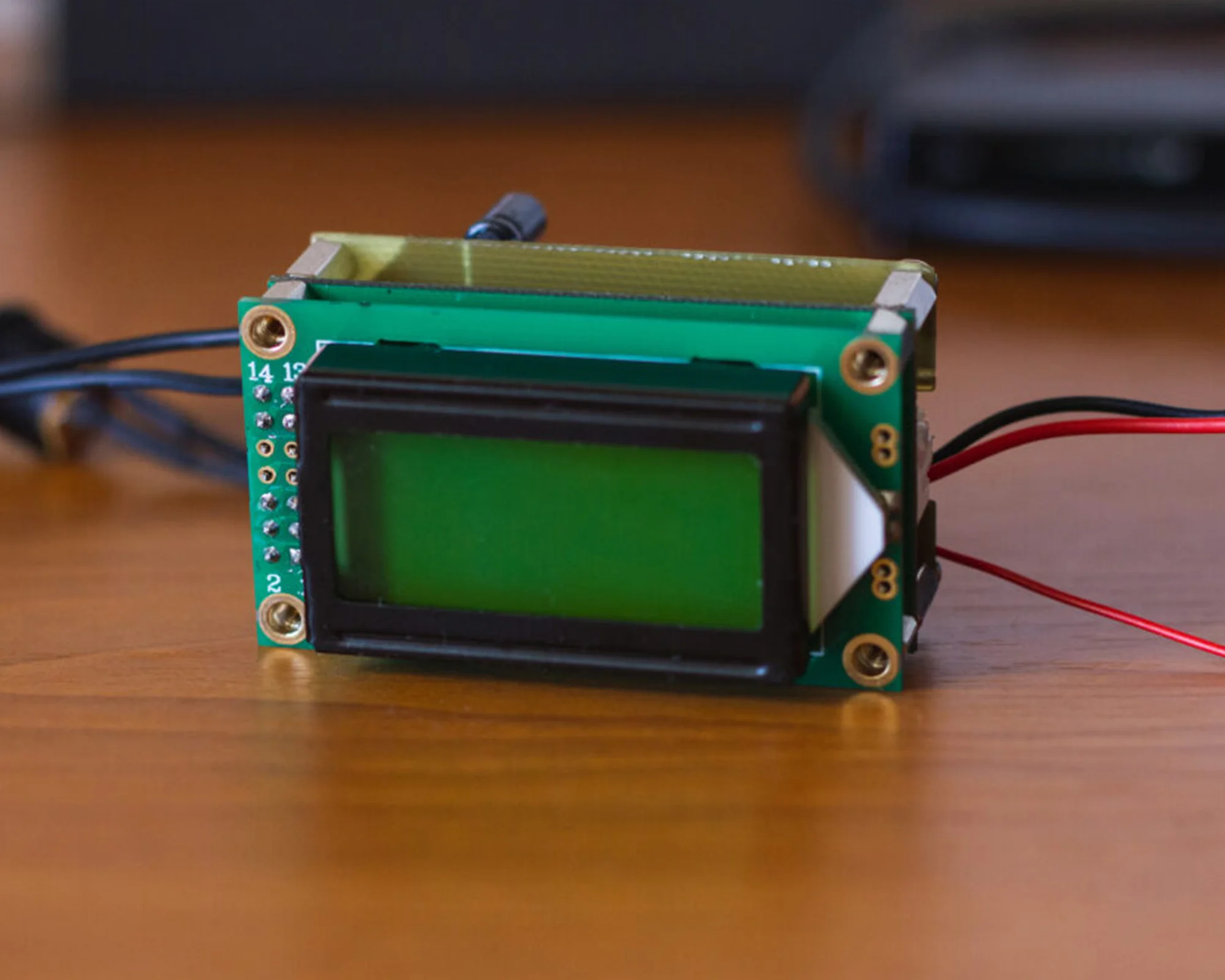
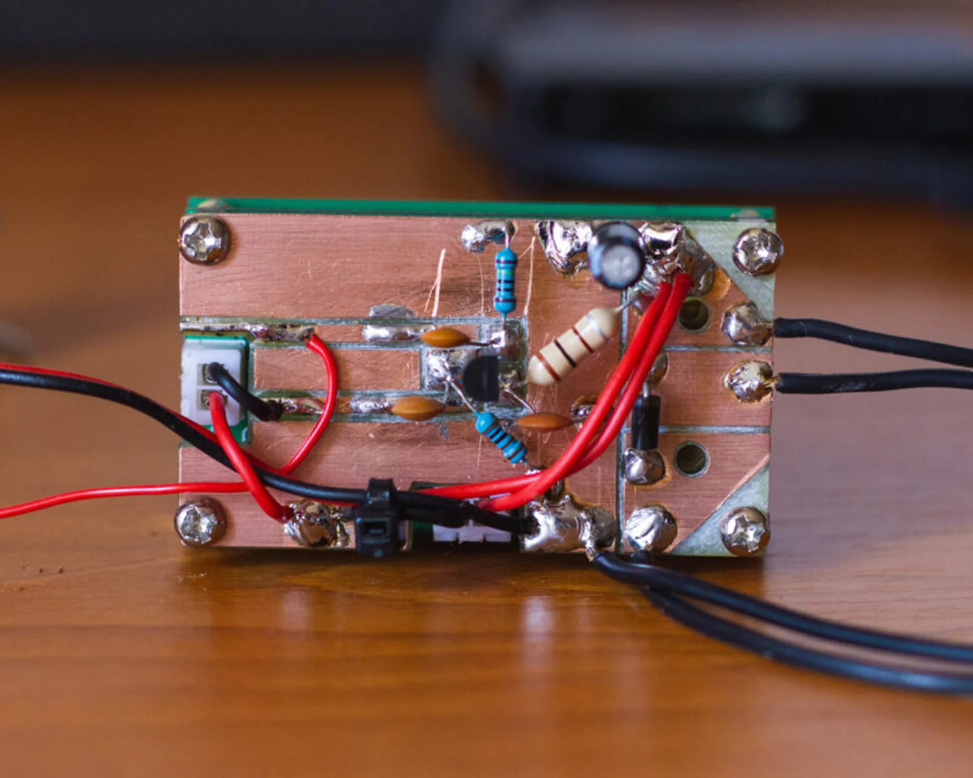
Frequency Counter With Preamplifier Circuit
Final Thoughts
This project it’s great for beginners or amateur radio operators who simply want to enjoy the weekend listening to the 80m band. The sensitivity of this receiver it’s less than -120dBm ( 0.2μV ). I was impressed by the frequency stability and the quality of the received signal. I made small changes to the value of some components according to my personal preferences. C14: 470 μF because it helps eliminate interferences. C24: 470 μF if listening through a speaker. It will reproduces low frequencies better this way. For listening through headphones or a smaller speaker, a 100 μF capacitor it’s a better choice. C19: 47nF or 100nF Mylar capacitor to cut off some of the high frequencies. C16, C17 and C18: Mylar capacitors because they seem to perform much better in an audio circuit than ceramic capacitors. These are personal preferences that help me have a great sound.
The receiver also works in other HF amateur radio bands. As an example, it can be modified for any amateur radio band from 160 m to the 10 m band. With a little imagination you can even make a multiband receiver quite easily. I hope you will love this receiver as much as I do. Good luck to all of you that would like to build it and I hope you won’t have any difficulties.
73, YO6DXE.