

Do you enjoy the content ? DONATE with PayPal to support me !
Get $5 of NEW USER FREE CREDIT using PCBWay. Full feature custom PCB prototype services, PCB assembly, SMD stencils, CNC / 3D Printing.
The $3 Pixie Transceiver Kit
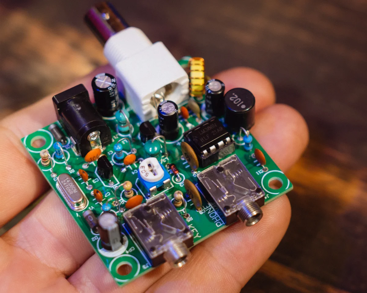
Get your cheap $3 Pixie transceiver kit ready for DX on the 20m band. Let’s see how far you can get with only 500mW of output power and minimal modifications to the original Pixie transceiver kit. I am planning on building a custom Pixie transceiver soon and design a new PCB board as well. For now here is a quick method of making little changes to the cheap Pixie transceiver kit you can find on AlliExpress. I used the simple version with no buzzer and LED’s.
When my own version of the Pixie will be ready, you will find an article about it here on the blog. Also the PCB board will be available on PCBWay together with the rest of my projects. You can order the PCB board if you like it and you want to build a custom Pixie transceiver.
Pixie Transceiver Schematic - 20m Band
Because online I found many of the schematics with mistakes, here is one that I made just to make sure you have the right component values. We will talk in detail down bellow about the modifications I made to the 40m band version, so we can convert it to the 20m band instead.
I respected the component names same as it was in the original schematic of the Pixie transceiver kit. Also on the PCB board from the kit, the components have the same name. The two extra components I placed on the board and they are not in the original kit, are CE and LE.
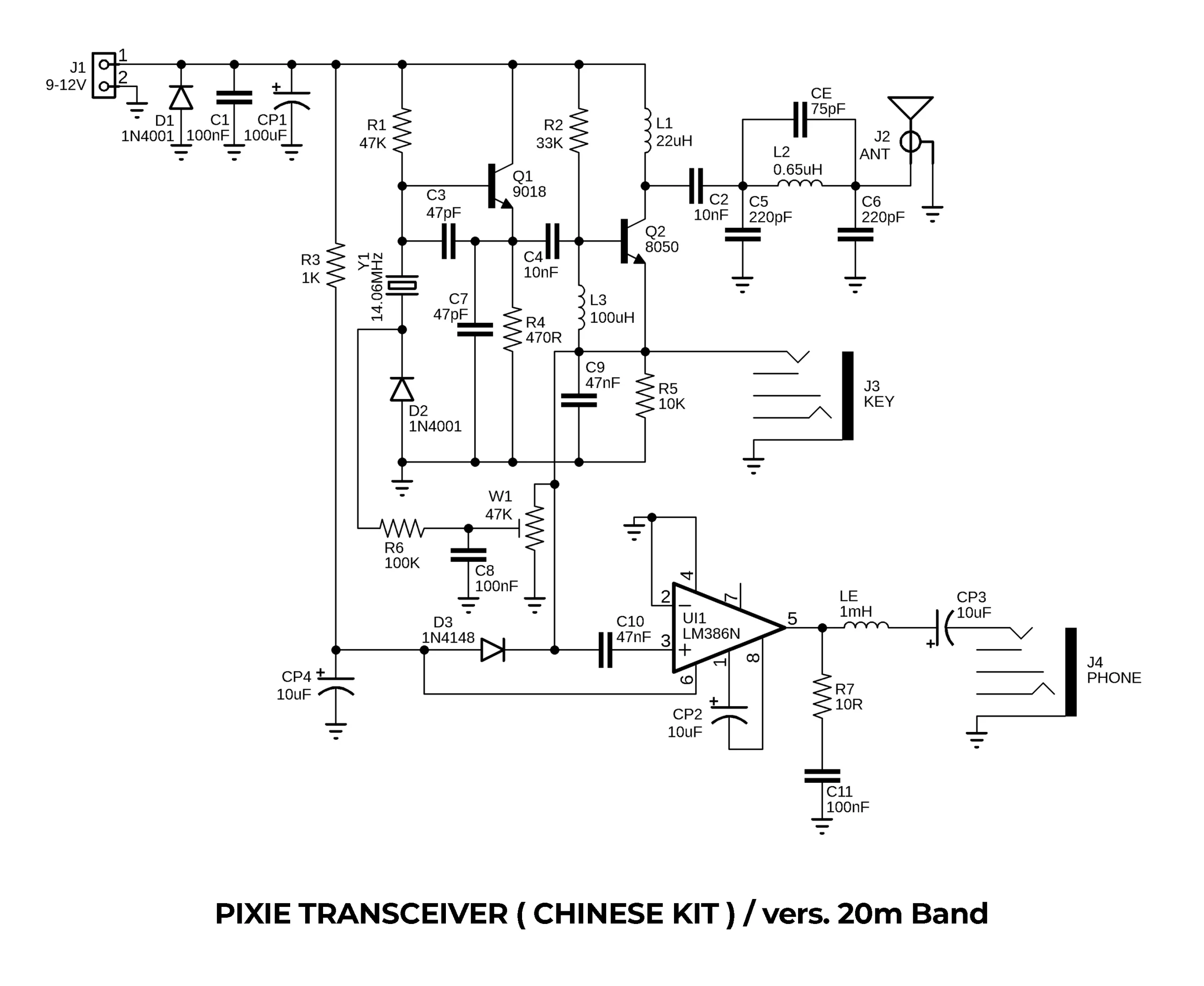
Pixie Transceiver Schematic – 20m Band
The Oscillator
I think is pretty obvious that the first thing we replace in the Pixie transceiver kit will be the crystal. So in our kit today we will use the 14.060MHz crystal. Usually in the standard 40m band version C3 and C7 have a value of 100pF. For the 20m band I noticed that it performs a lot better if I use 47pF instead. I don’t know about the other bands just yet until I build it and test it for those bands as well. Feel free to experiment as well, don’t be shy as that is how we learn.
Audio Output Filtering
What bothered me on the Pixie transceiver was the extremely high pitch sound on the audio output. That is totally the opposite when you want to listen to a more mellow CW tone. To increase the low frequencies you can change the value of CP3 to 220uF. But here it depends on your headphones and their frequency response. For the ones I am using today, I have better results with only 10uF, so I left it as it was in the kit. Also to cut down the high frequencies I placed the 1mH inductor ( LE ). For this one I had to cut the trace on the PCB board and solder it like that.
I have to point out that the inductor will only affect the audio output when listening into the headphones. If using an external powered speaker it will not change the audio output. Most of the time besides the headphones, I also use this amplified external speaker that sounds great.
Low Pass Filter
Here there is not much to modify. One thing I have to mention is that no matter what band I am building it for, I never use the original axial inductor from the kit for L2. Because I always had better results this way, I replace L2 with a toroid version. In our 20m band version, you must use a T37-6 yellow toroid. Wind 12 turns of 0.4mm or 0.45mm enameled copper wire. The inductance should be close to 0.65uH ( not mH as I specified in the video, my bad ). Down bellow you will have details of the low pass filter for other bands as well. Because for the 40m band C5 and C6 were 470pF, in the 20m version we will replace these with 220pF instead.
To lower the 2nd harmonic that usually is way to high and the output of the transceiver is not respecting the regulations, we will place on the back of the PCB board ( in parallel with L2 ) the capacitor CE. For the 20m band this one has a value of 75pF. This will lower the 2nd harmonic to a decent level so we do not create interferences and we also respect the regulations.
Pixie Transceiver On Other Bands
As I was saying, you can also modify the Pixie transceiver kit for other amateur radio bands. I have this list in my Modifications For The Pixie Transceiver article. You probably know from the video that I cannot stress enough on the quality of the ceramic capacitors used in the low pass filter.
Yes the cheap ones that come with the kit are fine if you measure them and they have the right value. But if you have the chance to replace them with good quality NP0 capacitors, is better.
Pixie Transceiver Bandpass Filter
| BAND | L2 | C5 / C6 | CE |
|---|---|---|---|
|
80m |
23 turns / FT37-6 |
910pF |
300pF |
|
40m |
17 turns / FT37-6 |
470pF |
150pF |
|
30m |
15 turns / FT37-6 |
300pF |
91pF |
|
20m |
12 turns / FT37-6 |
220pF |
75pF |
|
10m |
7 turns / FT37-6 |
120pF |
39pF |
The details for the bandpass filter were published in the Minimalist QRP Boook. I recommend it if you don’t have it yet. It has lots of simple and interesting QRP designs. I only built the 40m and the 20m versions so far and I was more than happy with the results.
Final Thoughts
The main question and the one that also makes me smile all the time is “What is the range of the transceiver ?”. This is how you know that the one asking is not an amateur radio operator. So the power output of the 20m band version of the Pixie transceiver was 500mW in my case. How far can you reach with this power ? It depends a lot on the propagation conditions. But one thing I must mention is that on the 20m band you have very weak chances to ever hear it on a local SDR receiver close to you. Is just the way propagation works on the 20m band.
If you want something for local coms, it’s better if you stick to the standard 40m band, or built an 80m band version. So you have more chances to hear your 20m band version in an SDR from other country. I hear this one on the SDR in Holland nice and clear. Of course now we must talk about the second thing that will influence the range of your transceiver, the propagation conditions. You can have days or moment during a day when you hear nothing and you won’t be heard anywhere. The band is simply quiet and you must wait. When the propagation conditions are great ( you will clearly hear that if listening ), that is your chance to make a contact. To be successful with the Pixie transceiver you need patience and good conditions.

The $3 Pixie Transceiver Kit
Many people say that this is just a toy because of the low power. Well if you use it well and you wait for good propagation conditions, you can make some really great contacts all around Europe from Romania. The best example for me is my friend Vlad – YO5BDL who makes CW contacts with only 10 to 100mW of output power with a simple dipole or vertical antenna. So if you really like these simple transceivers, it is possible to have some really great contacts.
Are you ready for serious DX on the 20m band with QRP power ? Good luck and good DX !
73, YO6DXE.

Thank you for the step by step, as a new ham it’s harder for me to follow the schematic, but these instructions should do it. Gonna order the pixie switch too! Thank you.
Always a pleasure my friend. If there is anything you don’t understand and if I can help, feel free to reach out.
73, YO6DXE.
SY1CRR
Thank you for reading Theodor.
73, YO6DXE