

Do you enjoy the content ? DONATE with PayPal to support me !
Get $5 of NEW USER FREE CREDIT using PCBWay. Full feature custom PCB prototype services, PCB assembly, SMD stencils, CNC / 3D Printing.
Introduction
A minimalist CW transmitter built in less than ten minutes. With only a handful of components and a power output of 550mW @12V or 350mW @9V. A great project for beginners in building amateur radio transmitters. I found the schematic in the Minimalist QRP Book. Miguel PY2OHH also built a version of this simple and cute CW transmitter. In the video above you have the first version I built. It had no low pass filter. Here in the article you have the updated 2025 version.
A version of this article was also published in the RADIO Magazine ( No. 5-6 June/July 2024 ), available in digital format translated in English downloadable as a PDF file.
The Schematic
I usually make modifications to most of the schematics, in order to get better performance. When I built the first version, I could not believe that it worked perfectly and didn’t need any adjustments. For that reason I kept the schematic as simple as possible. I added is a simple low pass filter on the output and modified the filter to improve the harmonics suppression. It’s not perfect, but it seems to do a decent job for the power output of the transmitter.
The circuit works as a low-power oscillator, capable of reaching 1W and currents of 100mA ( remember that the 2N2222 is for 80mA ). The transistor handles this current well in CW, but don’t keep the key activated for too long as the transistor will burn out. Another problem is operating without an antenna or a dummy load, the transistor will burn out.
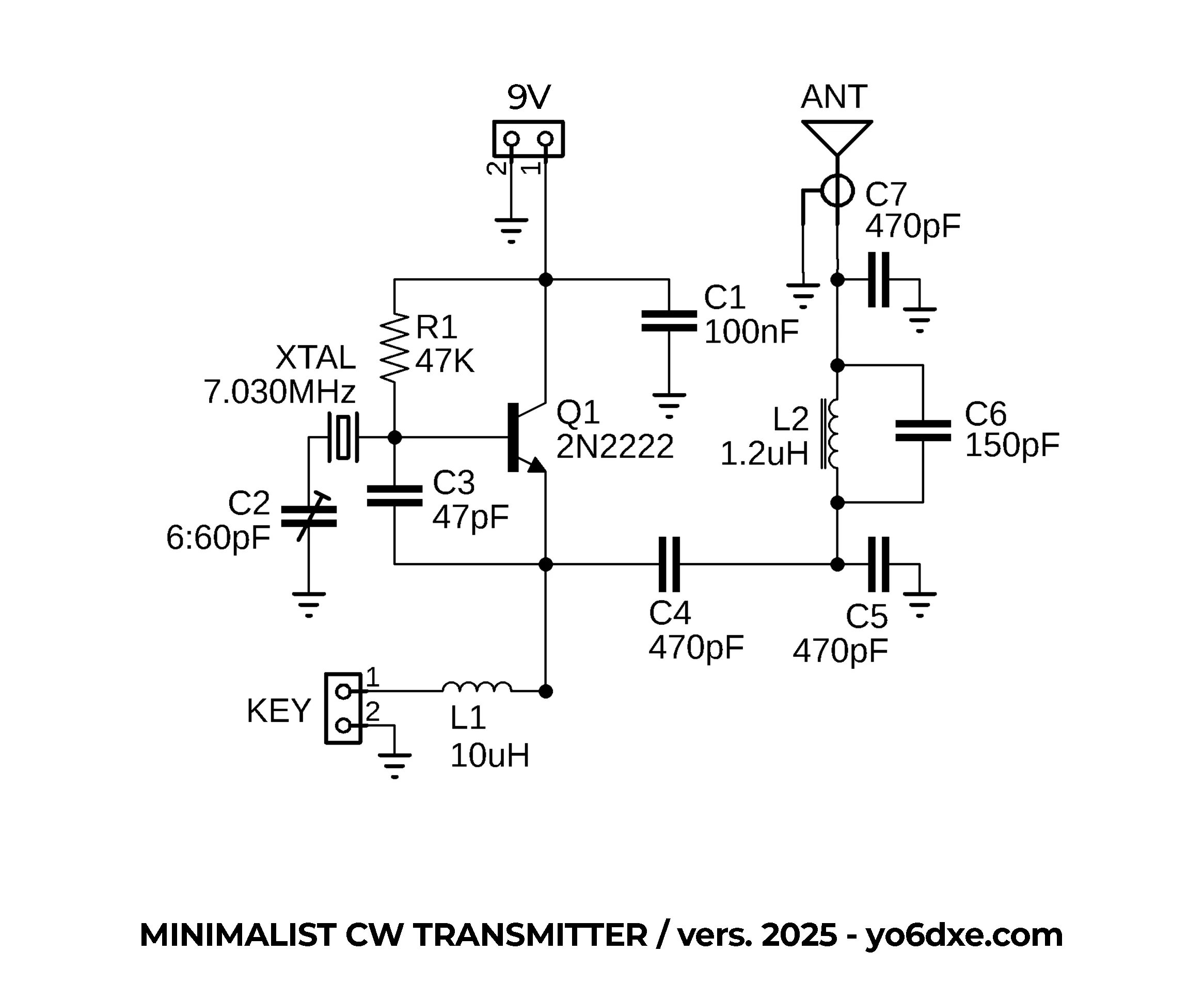
Minimalist CW Transmitter Schematic
Performance
With a simple TO-92 2N2222 you will get about 550mW output power. I am sure that with a better transistor you may be able to squeeze a little bit more power. At some point I used a TO-18 metal can 2N2222A transistor since the plastic TO-92 one it’s getting quite hot sometimes. I was not so happy with the power output of the TO-18, so I returned to the original TO-92 version. I usually power it with 9V instead of 12V so the transistor doesn’t heat up as much. If using a 2N2222 with a good Beta, you can reach 700mW powered @ 12V. Also in most cases I use a 7.030MHz crystal since that is the QRP calling frequency on 40m band.
Even with 350mW in CW you can still do contacts all over Europe from Romania. Another great thing is that it doesn’t have any chirp. It sounds great and has a beautiful tone. Together with a simple receiver, you can start doing some QSO’s in no time.
The version in the schematic it’s for the 40m band. I also tried a 20m version but I was not so happy with the results. So I would recommend it for the 40m band. Feel free to experiment and modify it for other bands as well if you really want to. I replaced L1 with a 10uH axial inductor because I used the same in the Pititico CW Transceiver with good results. If you take a look at the schematic of the Pititico CW Transceiver, you will notice that it’s really easy to convert this simple transmitter into a CW transceiver. Using the same modifications and an LM386 Audio Amplifier gives you the Pititico 2, almost a Pixie CW Transceiver.
The PCB Board
Using the toner transfer method, you can make a PCB board in less than 10 minutes. I started to find this a little annoying as they don’t always come out right from the first try. So now I prefer to order the PCB boards from PCBWay. Optionally you can build it Manhattan style as well.
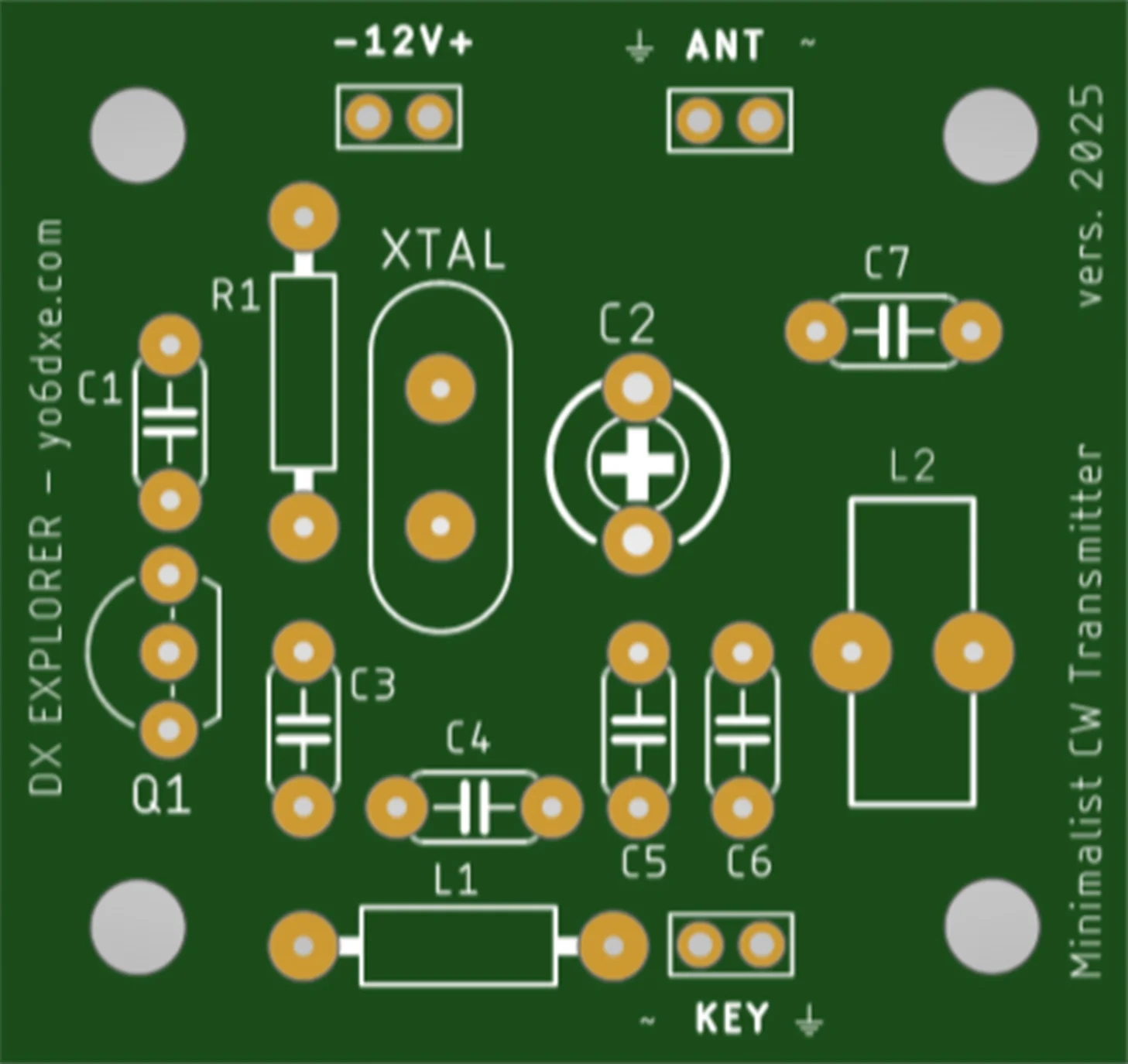
Minimalist CW Transmitter PCB Board
The 20m Band Version
In this video you have the 20m band version. It worked but I was not so happy with the results. The transistor was forced too much. It had some chirp as well so I decided to stick to the 40m band for this reason. I also built a little Spy Transmitter for my friend YO5BDL based on the 20m version.
The Final Version
When using a 7.030MHz crystal the transmit frequency was always a little lower ( around 7.029 MHz ). So I placed C2 in the schematic. This helps you adjust the capacitor so the transmit frequency it’s exactly on 7.030Mhz. If it doesn’t bother you transmitting at 7.029MHz feel free to replace C2 with a jumper wire. In the photo you see the blue connectors. I placed those just to avoid soldering and unsoldering wires while making tests. Normally I use small pins. The final assembled version also uses those pins, not the connectors. The space on the PCB board is a little tight for the connectors.
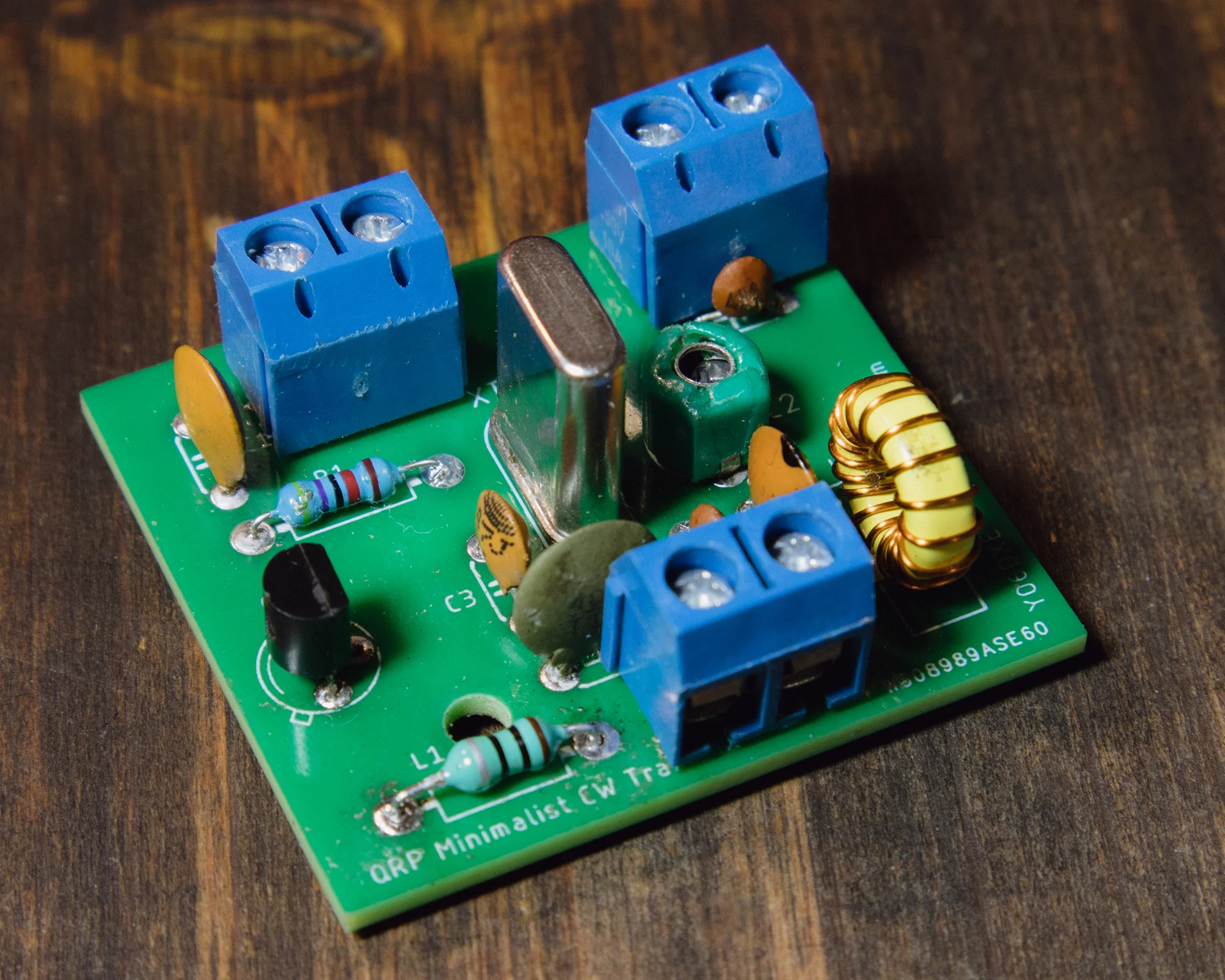
Minimalist CW Transmitter
The Low Pass Filter
The inductor L2 it’s recommended to be made on a T37-6 toroid. It has 17 turns of 0.4mm enameled copper wire. I measured 1.2uH when I tested mine out of curiosity. The low pass filter it’s a modified Pi-Network filter. I got the details of the filter for various bands from the Minimalist QRP Book. The details where in the Tiny Tornado CW Transceiver ( a version of the Pixie transceiver ) designed by KA8MAV. The filter it’s not perfect, but it’s way better than the standard Pi-Network low pass filter used in the Pixie transceiver kits. If you have the expected power output, I don’t think there will be any adjustments necessary to the filter. You can adjust a little the distance between the turns on the toroid to see if you can get better results.
I did not used a standard axial 1uH inductor as in the Pixie kits because I get way better results using the toroid version. This is valid both for the suppression of the harmonics, but also the power output of the little transmitter. If you do a scratch build, feel free to replace the filter with a better one if you want. I used the Pi-Network low pass filter because I wanted to keep the components count to a minimum. From a practical standpoint at this power level, the harmonics level should not cause any issue. If an antenna tuner is used, it will likely reduce the harmonics level even more.
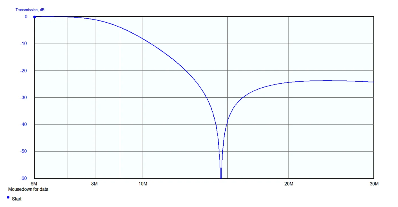
40m Band Pass Filter Simulation
I am wishing you good luck building this fun minimalist CW transmitter. It’s really tiny and easy to build by beginners. Feel free to experiment using other transistors as well. Also by changing the value of C4, you may be able to increase the power output. I had the best results with C4 having a value of 470pF. Just keep an eye on the transistor so it will not overheat. If you keep the key pressed for about ten seconds and the transmitter it’s not stable in frequency, chances are the transistor it’s overheating. Also if there is any chirp, that is usually from the same reason.
Rob KC4NYK built the transmitter and was picked up on the reverse beacon network 233 miles north from his location. The power output he had was only 300mW. Congrats Rob for this. I really need to learn the code as well so I can test the equipment I am building and have fun with it making contacts.
73, YO6DXE

Je cherche un transceiver trx 40 metre en qrp 73
I am working on a little project for a QRP transceiver as well. It will be some sort of improved version of the simple Pixie CW transceiver.
73, YO6DXE
Where can I pay for a unit assembled and tested ?
I am in Florida USA.
Good day Franklin. Sorry for the late reply. Right now the only place to order an assembled version is from PCBWay on the page where people order PCB boards. Over there there is also the possibility to order the assembled version. Unfortunately there is no testing involved, but the transmitter should be fine with no extra adjustments needed after the latest updates I made. 73, YO6DXE.