
Do you enjoy the content ? DONATE with PayPal to support me !
Get $5 of NEW USER FREE CREDIT using PCBWay. Full feature custom PCB prototype services, PCB assembly, SMD stencils, CNC / 3D Printing.
Introduction
I always loved the Pititico CW Transceiver designed by Miguel – PY2OHH and wanted to incorporate an audio amplifier in the circuit. This way I could use regular headphones. Here you have the 2025 version with a few modifications. You want to get on air for cheap ? I think you can build this for $10, or even less than that. It’s not perfect, but it’s a simple and easy to build CW transceiver. Initially I wanted to try the Curumim, also designed my Miguel. Since he was not so satisfied with it, I decided to use a few more parts and make a better Pititico.
A version of this article was also published in the RADIO Magazine ( No. 1 August 2023 ), available in digital format translated in English downloadable as a PDF file.
The Schematic
I found the original schematic designed by PY2OHH long time ago and I built a few versions in the past. Recently one of the YouTube subscribers ( Jesus ) asked me for help in a school project. He had to build a very simple CW transceiver for the 160m band. I thought it would be the perfect time to test this idea and see if it works. I was happy to realize that it works amazing, even on the 160m band with little changes.
There is nothing original in the circuit. All I did was to combine two circuits together. Miguel’s Pititico CW Transceiver, with an LM386 Audio Amplifier. Of course I had to make some adjustments in order to get it to work properly, but it was worth it. It feels a lot like a Pixie transceiver, but with less parts needed to build it.
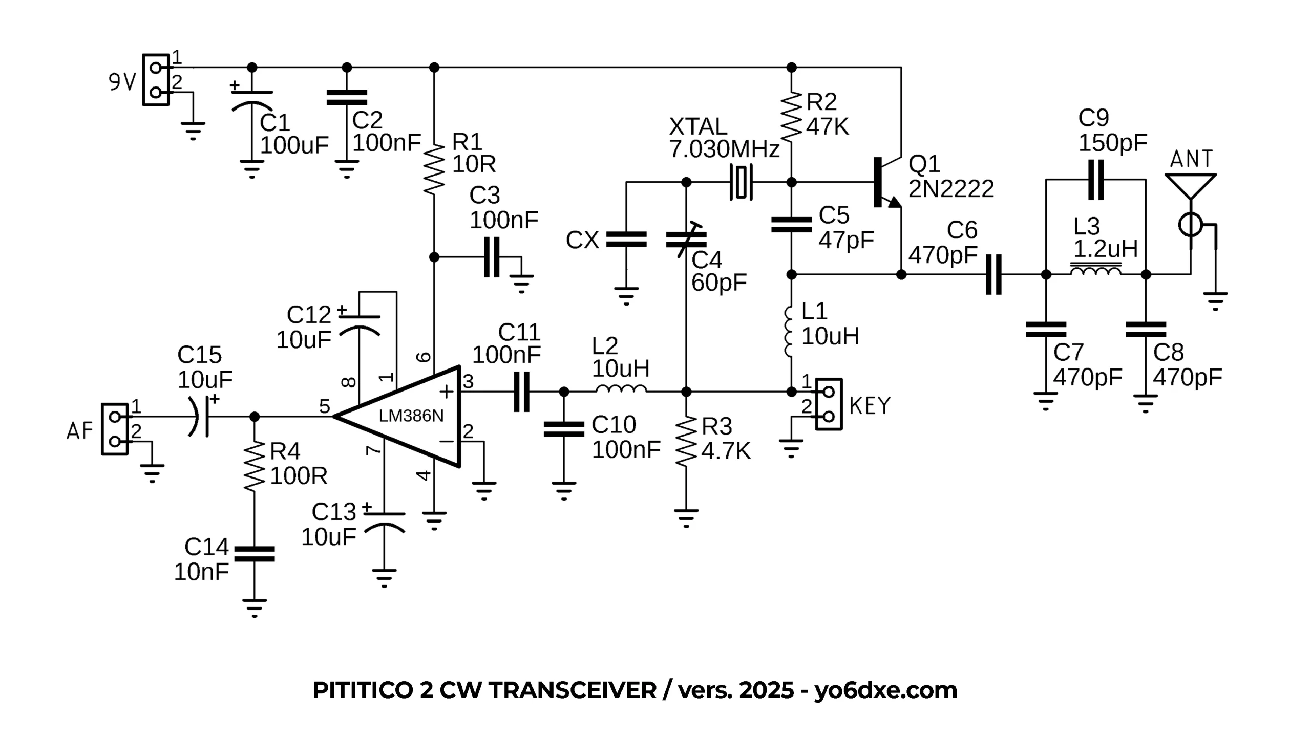
Pititico 2 CW Transceiver Schematic By YO6DXE
I will not go through all the info one more time as I already wrote important notes on the transceiver in the blog article on the Pititico CW Transceiver. Please go over and read that article as well to learn how to setup the RX offset frequency and the TX frequency. It makes no sense to write twice about the same thing. Google may also take it as duplicate content.
The new schematic was slightly modified from the original. I would recommend 9V with 350mW as the transistor doesn’t heat up so much. C4 allows you to tune the transceiver slightly. I added this one so I can tune it exactly on 7.030MHz. CX it’s an empty spot for optional frequency offset adjustments. More on this in the article on the Pititico.
L2 and C4 were added to minimize the strong AM broadcast band interferences. On YouTube I also have other various versions with more or less modifications. This latest update offered me the best results so far. Miguel used it with a telephone speaker as audio output. Since that didn’t worked for me, I incorporated the LM386 audio amplifier into this circuit. This one only works with regular headphones, or you can use an external amplified speaker.
Performance
I would compare it with the Pixie CW Transceiver as it performs nearly identical, both in the transmit power and also on receive. With a simple TO-92 2N2222 you will get about 550mW output power. I am sure that with a better transistor you may be able to squeeze a little bit more power. At some point I used a TO-18 metal can 2N2222A transistor since the plastic TO-92 one it’s getting quite hot sometimes. I was not so happy with the power output of the TO-18, so I returned to the original TO-92 version. I usually power it with 9V instead of 12V so the transistor doesn’t heat up as much. If using a 2N2222 with a good Beta, you can reach 700mW powered @ 12V.
The only down side is the receive sensitivity. It doesn’t seem to be that great, but you will hear stronger signals pretty good. I generated a signal with my TinySA and around -78dB I could barely hear the signal. Don’t expect much in the days with poor propagation conditions.
The PCB Board
Using the toner transfer method, you can make a PCB board in less than 20 minutes. In the video you hear me talking about the issues with the low pass filter and the AM broadcast band interferences. For that reason I updated the schematic and the PCB board with the improved version. Just build it as in the schematic and it should work right away.
Or you can order PCB boards from PCBWay. There is also available as an assembled version. I wanted to make it smaller, but it was hard to do so and still keeping it easy to make using the toner transfer method. It can be build a lot smaller if you want to.
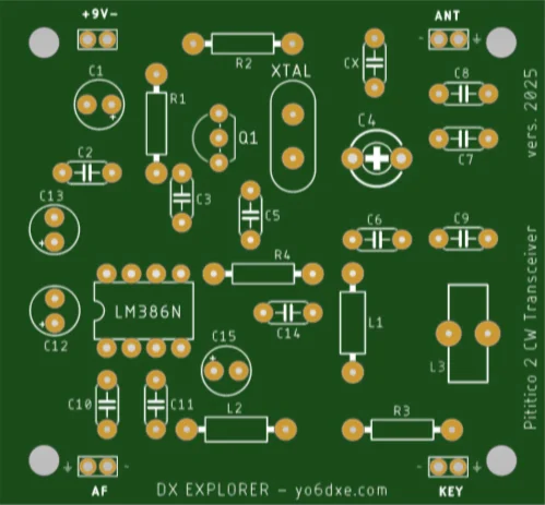
Pititico 2 CW Transceiver PCB Board
Older Versions
In this video I tried doing more improvements, but since I had a limited knowledge, I still had some issues I was trying to figure out. I am happy now with the 2025 version.
Here you have the first prototype of the Pititico 2. If you watch all three videos you will also notice how I tried finding various solutions to problems back then. It was a great project to work on as I learned a lot.
The Final Version
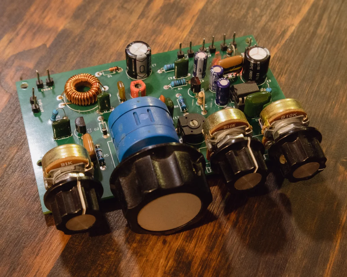
In the photo you see the blue connectors. I placed those just to avoid soldering and unsoldering wires while making tests. Normally I use small pins. The final assembled version also uses those pins, not the connectors. The space on the PCB board is a little tight for the connectors. Here you can also see the trimmer capacitor I used to have instead of the empty space for CX.
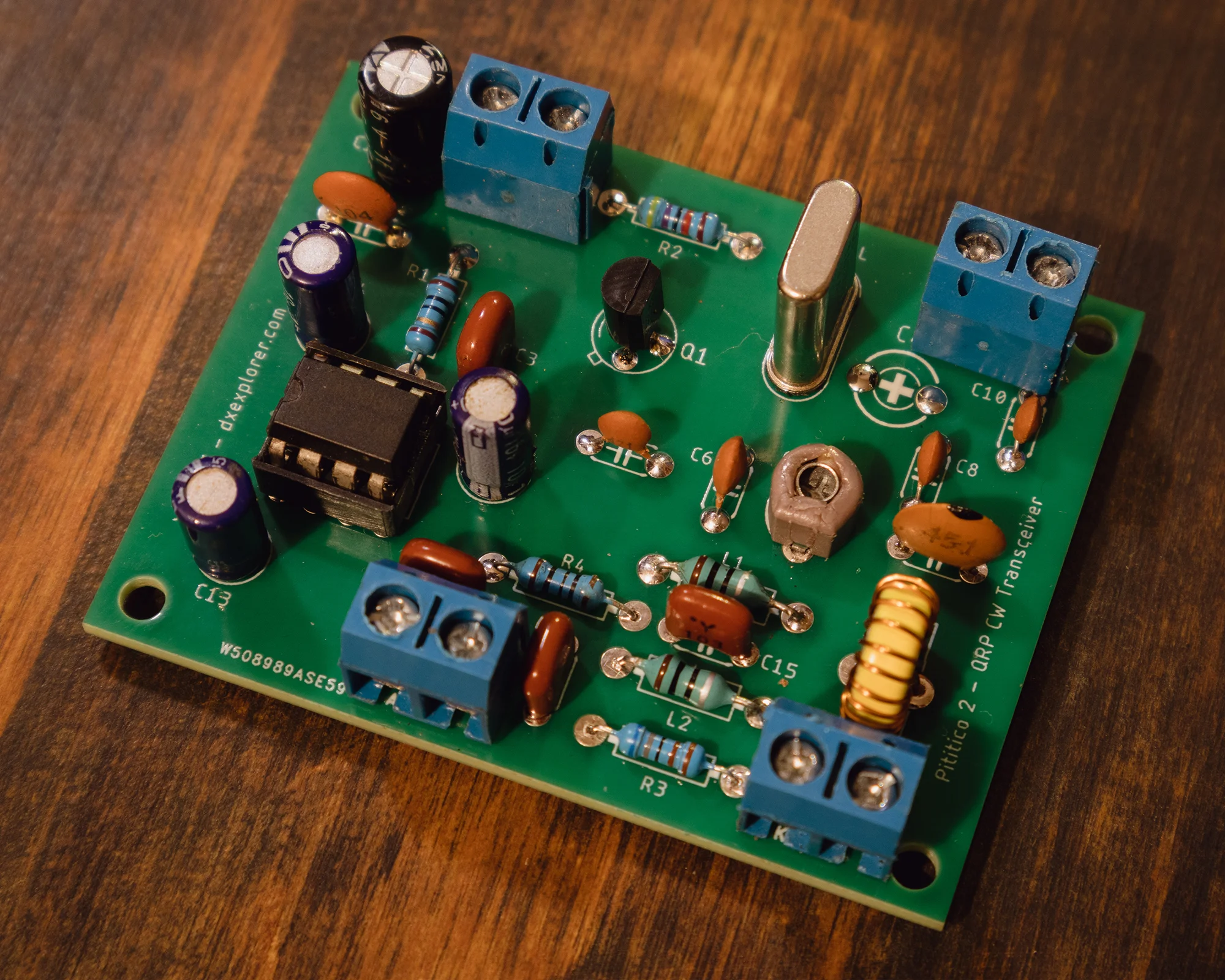
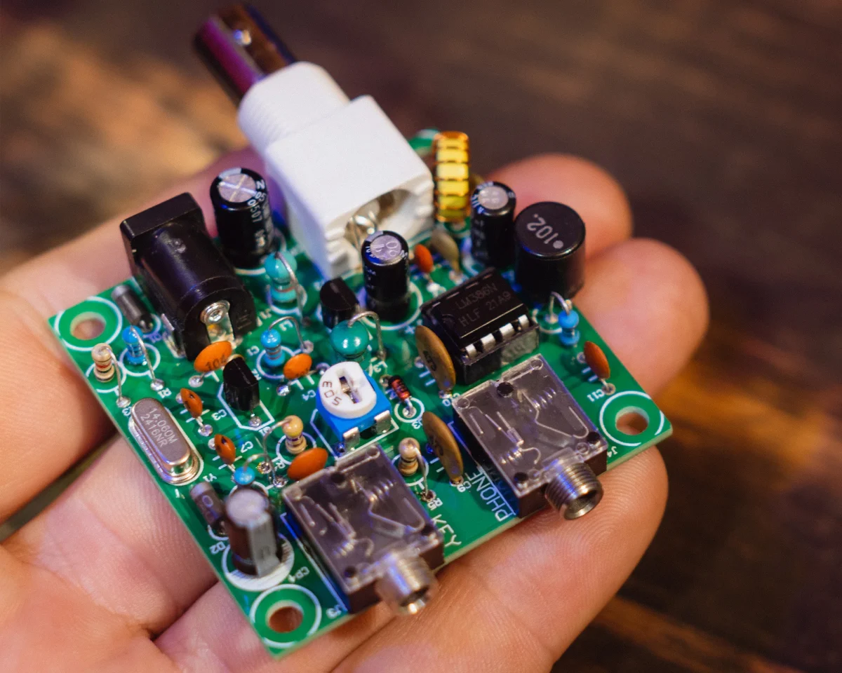
Pititico 2 CW Transceiver
The inductor L3 it’s recommended to be made on a T37-6 toroid. It has 17 turns of 0.4mm enameled copper wire. I measured 1.2uH when I tested mine out of curiosity. The low pass filter it’s a modified Pi-Network filter. I got the details of the filter for various bands from the Minimalist QRP Book. The details where in the Tiny Tornado CW Transceiver ( a version of the Pixie transceiver ) designed by KA8MAV. The filter it’s not perfect, but it’s way better than the standard Pi-Network low pass filter used in the Pixie transceiver kits. I used the Pi-Network low pass filter because I wanted to keep the components count to a minimum. From a practical standpoint at this power level, the harmonics level should not cause any issue. If an antenna tuner is used, it will likely reduce the harmonics level even more.
Ron WB5DYG built the older Pititico 2 CW Transceiver and while playing around he also made some modifications. You may want to have a look at his video, or you can download his PDF notes. You may find various other ways to further improve this simple design. Some of his notes are also valid for this simple version of the transceiver.
I am wishing you good luck building the Pititico 2 CW Transceiver. It’s really tiny and easy to build by beginners. Feel free to experiment using other transistors as well. Also by changing the value of C6, you may be able to increase the power output. I had the best results with C6 having a value of 470pF. Just keep an eye on the transistor so it will not overheat.
If you keep the key pressed for about ten seconds and the transceiver it’s not stable in frequency, chances are the transistor it’s overheating. Also if there is any chirp, that is usually from the same reason. You can also experiment with a BD139 if you do a scratch build of the transceiver. By lowering the value of R2 to 18K or even lower down to 4.7K if the transistor as a bigger Beta, you can get about 1W power output @ 12V. Experimenting is fun so I will say good luck and good DX.
73, YO6DXE