
Do you enjoy the content ? DONATE with PayPal to support me !
Get $5 of NEW USER FREE CREDIT using PCBWay. Full feature custom PCB prototype services, PCB assembly, SMD stencils, CNC / 3D Printing.
The Pixie Transceiver Kit
4 simple modifications for the Pixie transceiver kit. No AM broadcast band interferences, a side tone circuit and a VXO. There are all possible by making little changes to the original kit.
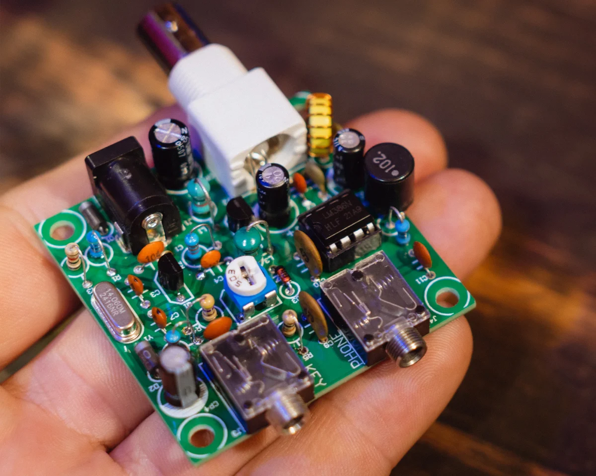
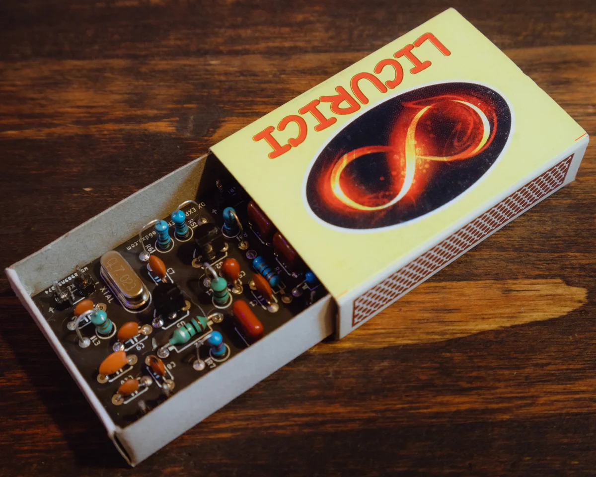
The Pixie transceiver kit became very popular and even now you can find kits available for sale. Cheap kits are available on AliExpress. There are also assembled versions as well, but harder to modify. Some as a simple version, with a buzzer, or in some cases with an acrylic enclosure. Many consider them a toy, but with a little patience and effort, you can get many contacts using this simple CW transceiver. Same as you can with the Matchbox Transceiver for example. QRP it’s like fly fishing, you need patience and good conditions. Down below you have a Pixie Transceiver schematic from one of the kits that comes with a buzzer for sidetone. Sorry for the quality but it’s a scan from one of the kits I purchased.
Many people modified the kits either for other bands, or to bring little improvements. In the video above you will see the modifications we will talk about in this article. Except the low pass filter as I changed my mind in the meantime and I no longer use what I had in the video. I had a limited knowledge when I made these modifications, but even like that it turned out well.
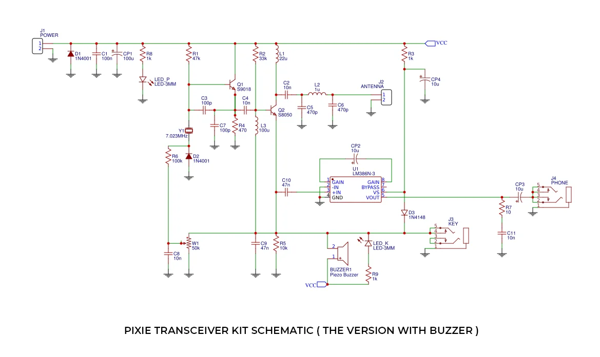
Pixie Transceiver Schematic
Pixie Transceiver Modified Schematic
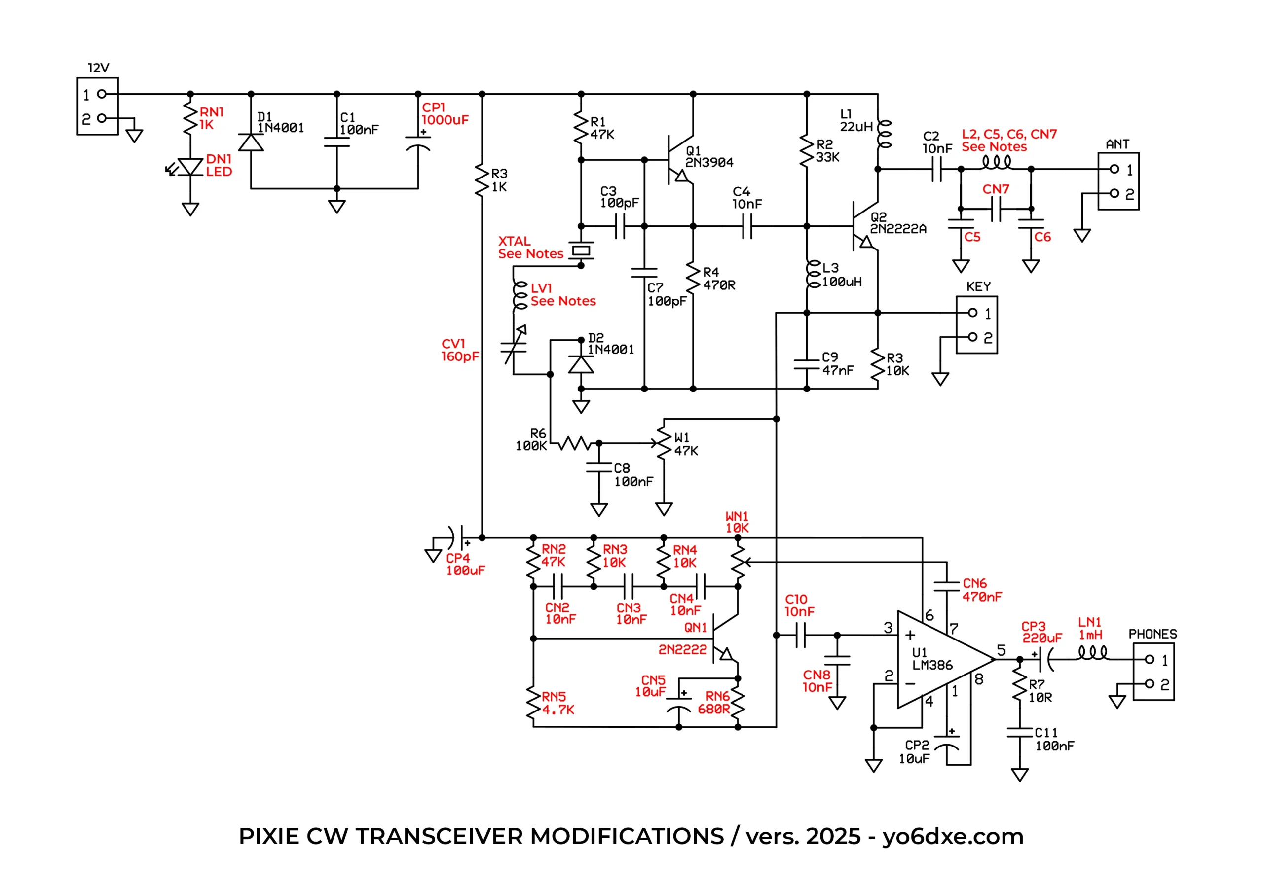
Down bellow you have the Pixie transceiver modified schematic. Pay close attention as the part numbers may not match with the schematic of the kit you have. But it should be pretty simple to figure out what changes I made. To make sure I do not create confusion, I made all the modifications to the original schematic in red. The version of the kit I used was the one with no buzzer for sidetone. All the modifications are optional and you do not have to make all of them. Pick the ones that you are more interested about. Down bellow we will talk in detail about all.
For those that would like to modify the Pixie for other HF bands, towards the end of the article we will also talk a little about the changes you need to make. There are modifications available for: 80m, 40m, 30m, 20m and the 10m band. The power output will vary depending on the transistors most of the time but also on what crystal you use and on what band. Usually the power of a Pixie transceiver could be between 250mW up to 750mW. This depends a lot on the voltage you are powering it with and also the amplification factor of your transistors.
Modifications For The Pixie Transceiver
Power Filtering
The first modification I made was to replace the original 100uF capacitor With CP1 – 1000uF / 16V. I tried to find the smallest one in size that I could, so it will fit on the board. I also installed RN1 – 1K and DN1 – 3mm red LED as a power on indicator. I did not added a switch as I just plug in or out the power cable. The 1000uF capacitor helped me have a better DC filtering when using a wall power supply instead of a battery. By the way, you can power the Pixie transceiver with 9V or 12V. At 12V you may have a little more power output, but sometimes Q2 may overheat. If you power it at 12V sometimes you may need a little heatsink for Q2. At 9V there should be no issues.
Audio Output Filtering
One of the things that bothered me on the Pixie transceiver was the extremely high pitch sound on the output. That is totally the opposite when you want to listen to a more mellow CW tone. For that reason to increase the low frequencies I increased the Value of CP3 to 220uF. But here it depends on your headphones and their frequency response. For the ones I am using today, I have better results with only 100uF. Also to cut down the high frequencies I placed the 1mH inductor. For this one I had to cut the trace on the PCB board and solder it like that. Most of the time besides the headphones, I also use this amplified external speaker that sounds great..
Pixie With VXO
Because the Pixie it’s stuck to the frequency of the crystal ( usually 7.023MHz ), we will change the circuit and add a VXO. For this I placed CV1 – a simple PVC film variable capacitor around with two options 140pF and 60pF. I used the 140pF side of the variable capacitor. In the video I made I did not used an inductor as you see in the schematic. You can extend the frequency range by also using an inductor. Here is the tricky part. The value of the inductor depends on the crystal you are using and also the frequency of the crystal. I only tested this for the 20m band and a 10uH inductor worked perfectly. You may want to experiment and try other values depending on the band you are building it for. For the 80m band for example, you may have to use a larger value around 47uH or even 150uH. The sign that will show you if the value it’s too big is when the oscillator either stops oscillating, or when you transmit you have chirp and instability in frequency. Feel free to experiment until you find an optimal value. Usually I replace the crystal with a 7.030MHz version since that is the QRP calling frequency.
Sidetone Circuit
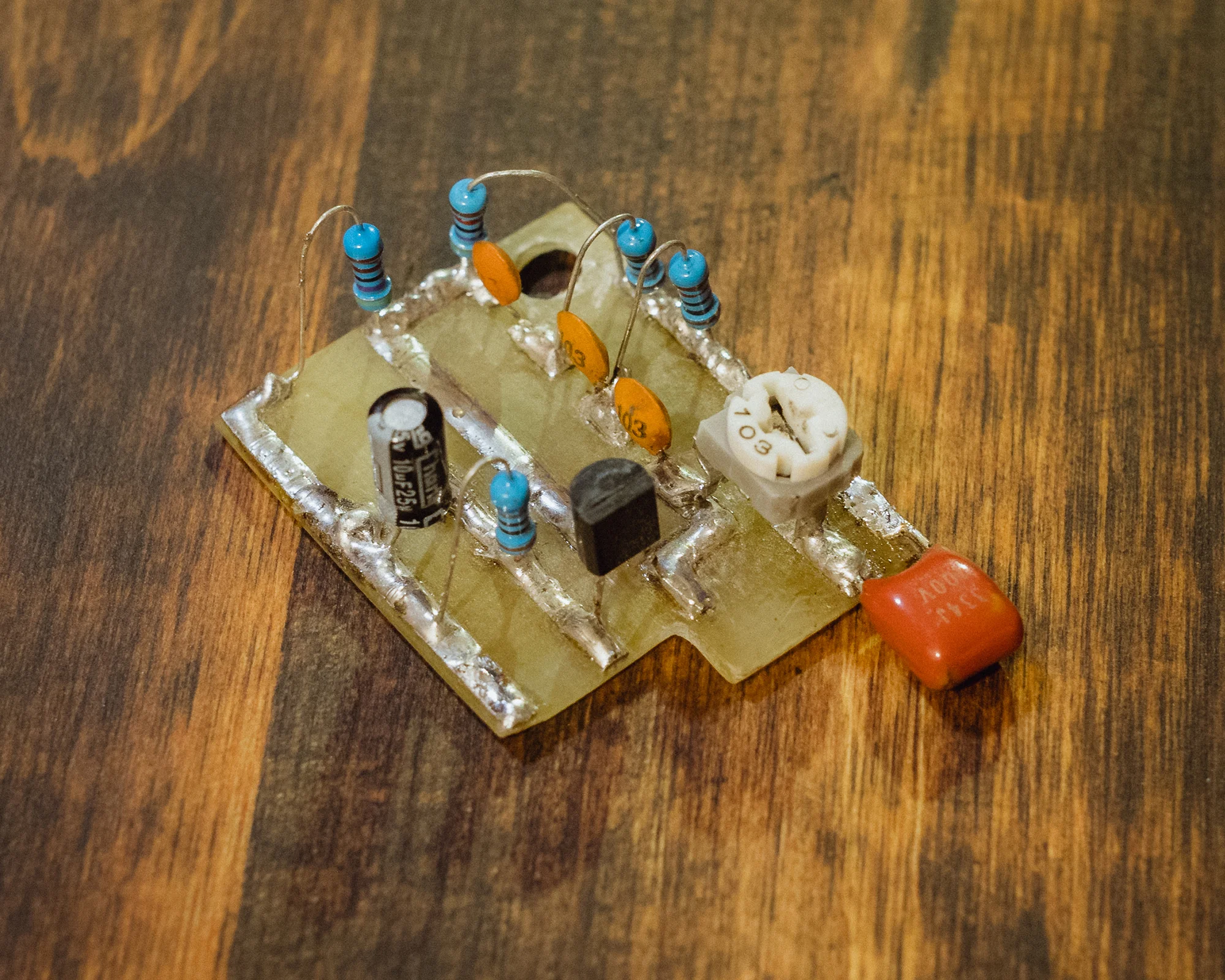
Initially I decided on the buzzer method since I did not had it in the kit I received. It is indeed a good option instead of not having any sidetone at all. But also the high pitch of the buzzer became really annoying after a while and I decided to find a different solution to this. So I ended up building a circuit thanks to a schematic from Sverre – LA3ZA. I must also say thank you to him as I had some issues getting it to work and he was kind enough to guide me until I got the sidetone circuit to work properly. It sounds really nice as you can hear in the video.
Sidetone Circuit For The Pixie CW Transceiver
You need to build the circuit separately on a little PCB board as I did here in the image. The hard part is drilling the Pixie PCB board in the right place to make the right connections. Actually many of the modifications we are talking about here, will require you to either cut or scratch traces of the original board. That is why I was saying at the beginning that you only do the modifications you are comfortable doing. I tried them all ( hi ) as I was curious. I did messed up the board at the end as I experimented with way more modifications than the ones here.
Low Pass Filter
In the video you may notice that I was talking about a modified low pass filter. I actually transformed it into a band pass filter. It was great in a way as it removed all the AM broadcast band interferences. The down side was that I also had a little lower power output. For that reason I returned to the usual Pi Network low pass filter. I do not use axial inductors like the one that comes with the kit. Instead I used a toroid core. There is also one extra capacitor added to lower the second harmonic. The filter it’s not perfect, but for this power output we should be fine and it should not create interferences on other bands.
When it comes to removing the AM broadcast band interferences, usually I just place an extra capacitor before the audio amplifier, CN8 – 10nF in the schematic. Unfortunately it will not always remove the interferences 100%. But at least the level it’s a lot lower and it won’t bother you that much. If you are lucky you may have no interferences at all. CN8 it’s an optional modification as many times it may lower the audio output of your transceiver. I would recommend you to temporarily solder the capacitor on the back of the PCB board of the Pixie transceiver in the right spot. If you are happy with the results, then solder it permanently.
Pixie Transceiver On Other Bands
Many people asked if it’s possible to modify the Pixie transceiver kit to work on other amateur radio bands. Down bellow you have the modifications you need to make to the values of the components from the low pass filter. You will do these modifications depending on the band you want to build your Pixie for. Of course the crystal you are using should be for that particular band as well. I usually purchase them from AliExpress as well because they are cheaper. In most cases the low pass filter and the crystal it’s the only change you have to make.
In some cases though, the oscillator may stop oscillating with some crystals depending on the band. Here we start experimenting again. Let’s take as an example the 80m band. First replace the crystal and the components of the low pass filter for the 80m band. Turn on the Pixie and if you have a receiver to listen to your Pixie transceiver, transmit in a dummy load and if you hear it then it should be fine. You can also measure the power output and see if this one it’s fine.
Usually on the 80m band the power output should be similar to the 40m band. On 30m, 20m and the 10m band it may be a little lower. But let’s think the worst and our Pixie does not oscillate. One option would be to increase the value of the capacitors C3 and C7 to a larger value for the 80m band. You can try 220pF or even more up to 470pF until you get it to work properly. For the 20m, 30m and the 10m bands the value you need it’s usually smaller than 100pF if the Pixie doesn’t oscillate. Most of the time there are no issues and it works fine with 100pF.
Pixie Transceiver Bandpass Filter
| BAND | L2 | C5 / C6 | CN |
|---|---|---|---|
|
80m |
23 turns / FT37-6 |
910pF |
300pF |
|
40m |
17 turns / FT37-6 |
470pF |
150pF |
|
30m |
15 turns / FT37-6 |
300pF |
91pF |
|
20m |
12 turns / FT37-6 |
220pF |
75pF |
|
10m |
7 turns / FT37-6 |
120pF |
39pF |
The details for the bandpass filter were published in the Minimalist QRP Boook. I recommend it if you don’t have it yet. It has lots of simple and interesting QRP designs. I only built the 40m and the 20m versions so far and I was happy with the results. Pick the enameled copper wire with a thickness that will allow you to fit the necessary number of turns on the toroid.
Final Thoughts
The Pixie Transceiver it’s fun indeed, both to build it and also using it. Far from perfect of course, but you can’t expect miracles from a handful of components. I like it even if it has little issues. I even like it as it comes in the standard kit. I do recommend modifying at least the bandpass filter of the usual kit you are buying. The one that the Pixie has it’s still full of harmonics. Making all these modifications ( some with lots of headaches too ), it was fun in a way but the most important is that back then I learned a lot from this. Here it comes the surprise now.
I do not know exactly when, but clearly sometime soon, I am planning on designing a new PCB board ( single layer ) for the Pixie transceiver. This one will be an improved version, thanks to all the experiments I made so far. It will also have a sidetone circuit, a simple CW filter that will also act as an audio preamplifier. With a little luck it may also work with a speaker not only headphones. By that time I hope I will also find a way to completely remove the AM broadcast band interferences. One last tip and I am closing the article. The Pixie CW transceiver was designed in a way to be built by many people using the values in the schematic. But you should know that by discovering and learning how the circuit works, you may be able to change a few values and improve the power output even more. All I will say is good luck experimenting and I hope this article was helpful. I learned a lot from this and I hope you will too.
73, YO6DXE.