

Do you enjoy the content ? DONATE with PayPal to support me !
Get $5 of NEW USER FREE CREDIT using PCBWay. Full feature custom PCB prototype services, PCB assembly, SMD stencils, CNC / 3D Printing.
Introduction
A matchbox transceiver, the ultimate minimalist radio setup. Ever wondered if you could transmit Morse code using something the size of a matchbox ? Today we’re designing a minimalist transceiver with only three transistors. A combination between the Pititico designed by Miguel – PY2OHH and the uu80b designed by Roger – G3XBM. The idea of placing it in a matchbox just like a secret spy CW transceiver comes from Helge – LA6NCA. In the video above I started from an improved version of the uu80b transceiver, converted for the 40m band.
The Schematic
Down bellow you have the schematic of the uu80b transceiver. I built this one in one of my older videos, but I wanted to take everything to another level. I did liked the original schematic, but I thought that a little improvement can’t hurt at all. Thanks to the idea from Helge of building a spy matchbox transceiver, I thought I should also give it a try.
The matchbox transceiver it’s one of the smallest and simplest transceivers designed around three 2N2222 transistors. With only a handful of components and a power output of 550mW @ 12V or 350mW @ 9V. A great project for beginners in building amateur radio transceivers. Since it’s so small it will require some patience and a lot of attention. Take this version as “one size fits all” kind of project. With a little tweaking you may able to get even better results.

uu80b Transceiver by Roger – G3XBM
The circuit works as a low-power oscillator ( Q3 ), capable of reaching 1W and currents of 100mA ( remember that the 2N2222 is for 80mA ). The transistor handles this current well in CW, but don’t keep the key activated for too long as the transistor will burn out. Another problem is operating without an antenna or a dummy load, the transistor will burn out. I would recommend to power it at 9V with 350mW output power as the transistor doesn’t heat up so much. C7 allows you to tune the TX frequency. I added this one so I can tune it exactly on 7.023MHz. Depending on the crystal used, you may have to change the value of C7. For the 7.023MHz crystal 47pF was optimal and we have both the TX frequency exactly on 7.023MHz and also the 800Hz offset frequency on receive.
If you will use a crystal for 7.020MHz you may have to increase the value up to 68pF, so it depends on the crystal. For C7 usually I would use a trimmer capacitor for easy adjustment same as I used for the Pititico. Because of the limited space, I decided to use a fixed capacitor instead. Since the transceiver uses a small 7.023MHz crystal the 47pF capacitor should be ok.
L1 and C6 were added to minimize the strong AM broadcast band interferences. Q2 it’s an audio amplifier stage. Q1 it’s a simple one transistor CW bandpass filter resonating around 600Hz ( it’s one transistor so do not expect miracles ). The audio output it’s meant for a high impedance earpiece. I had the best results with this one. It can also be used with regular headphones but the volume will be lower. Earbuds can be a better choice than big headphones. Most of the time I also use it with this amplified external speaker. It has no side tone so it’s more like a basic Pixie CW transceiver. The LPF on the output it’s not the best but it had to fit in a matchbox.
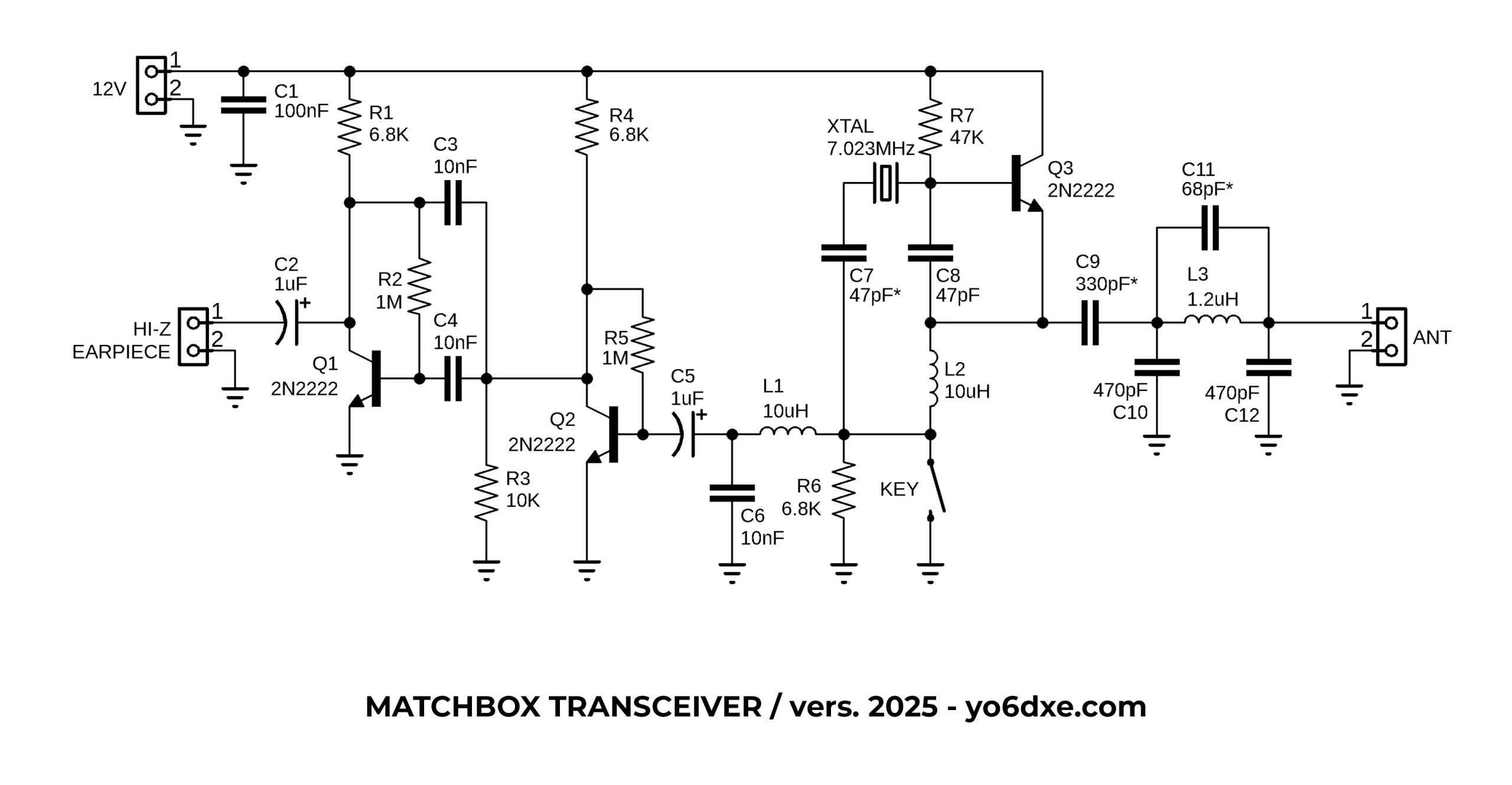
Matchbox Transceiver Schematic by YO6DXE
Performance
Just like the Pititico or the Pititico 2 transceivers, the Matchbox Transceiver has nearly the same performance ( almost like a Pixie transceiver ). The receive sensitivity it’s not the best but in days with good propagation you do hear a lot. When I originally built the uu80b transceiver, I had a lot of interferences from strong AM broadcast stations. With all the modifications I managed to reduce those to a minimum, but you can still her them now and then. Because the receiver’s front end is wide open, I decided to use a 3rd transistor for a simple CW filter.
In the image down below you see on the mini oscilloscope that the filter resonates well at almost 600Hz ( 562Hz ). It’s not a very sharp filter but it helps in having a higher audio level on the output. Also it does seem to do a good job as a filter as it helps me copy weaker stations that normally I wouldn’t be able to copy with the original uu80b transceiver.

CW Filter Center Frequency
The PCB Board
For this project I would recommend you to order the PCB boards from PCBWay. Due to the size of the matchbox, I just couldn’t fit all the components on the board and using a single layer PCB board. So it has bot top and bottom. Remember that I only use THT components I do not use SMD. The top layer it’s the ground and on the bottom you have the circuit of the transceiver. In the download folder you do have the files to make PCB boards using the toner transfer method. Because it’s a 2 layers PCB board I honestly think that it’s a lot easier to build it Manhattan style. But if you want to try the toner transfer method, the files are there. If you use the toner transfer method please remember to solder the components both on top and also on the bottom layer since there is no connection between the two layers as it would be in a PCB board from PCB Way.
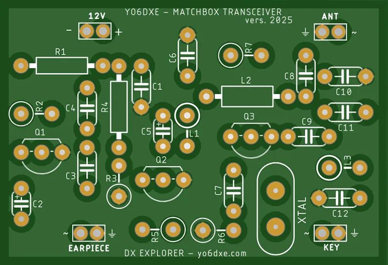
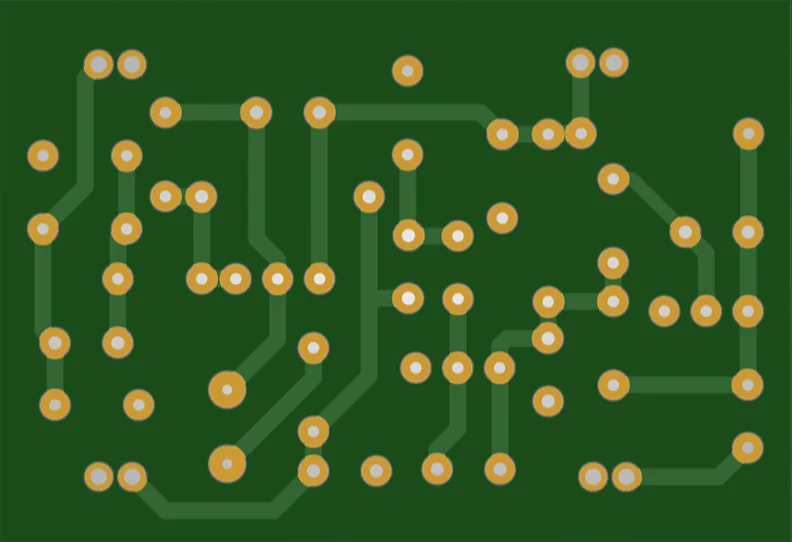
Matchbox Transceiver PCB Board
I initially had an error on placing C5 the right way. I spoke about this in the video. So if you built it using the older schematic and PCB board design, please fix that issue and it should be fine. Unless you decided to use non polarized capacitors as those are fine and don’t create issues.
Low Pass Filter Performance
Same like the Pititico, this transceiver also uses a modified PiNetwork low pass filter. Usually with a toroid inductor I get a little more power output. Since it had to fit everything in a matchbox, I decided to use an axial inductor. The performance with this one it’s a little lower, but not by much. For this power level it should be good enough and I do not think it will create any issues. In the first image you can see the level of the oscillator in stand by, RX mode. That can be lowered by increasing the value of R6 to 10K, but it will influence both the reception sensitivity and also the frequency offset. For that reason I picked the value of 6.8K.

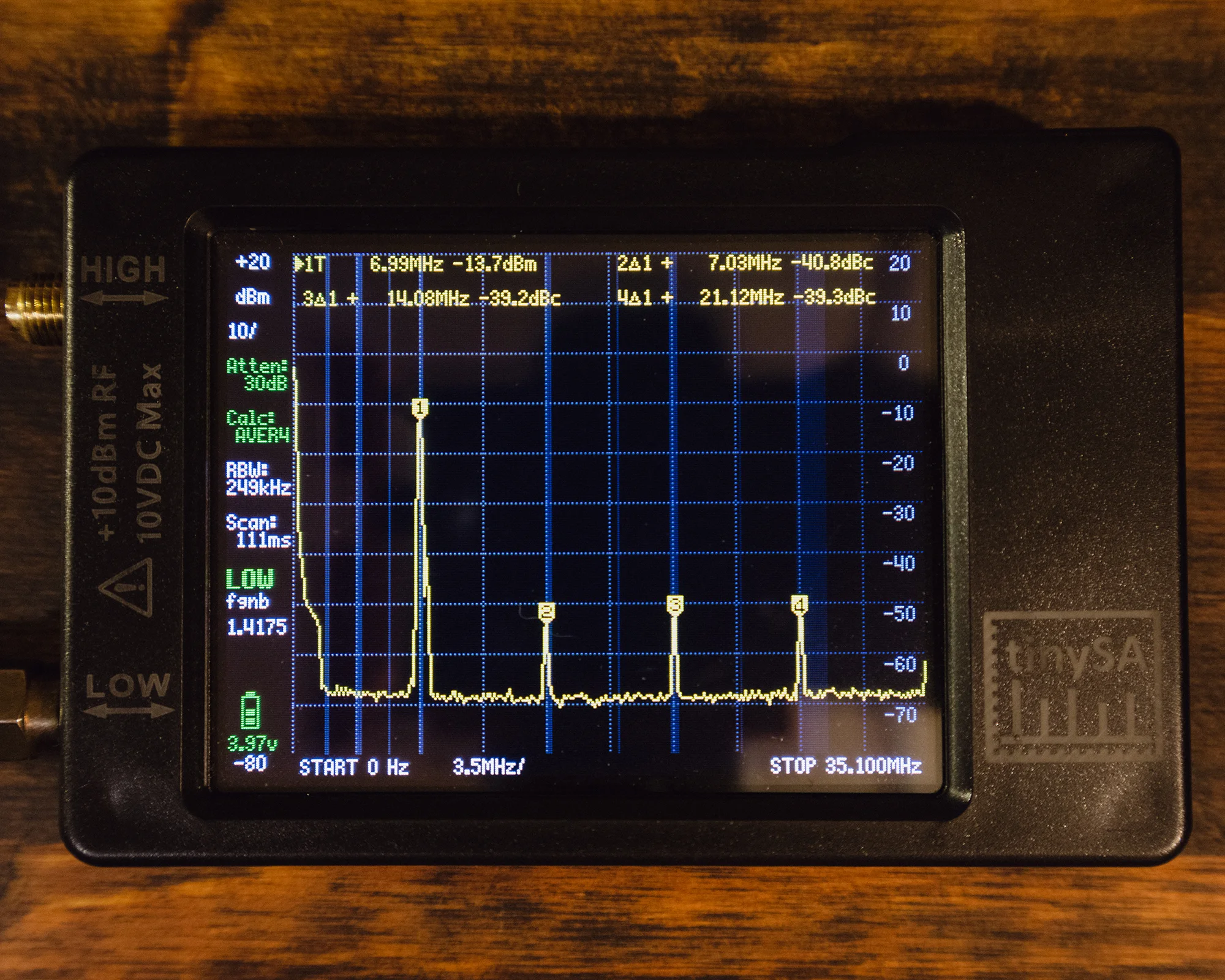
Harmonics Level On TX
The Prototype
This was the first test and the breadboard prototype for my matchbox transceiver. It worked great, but I knew I could improve it even more and I am happy I did.
uu80b CW Transceiver
Here is a video with the first built of the uu80b CW transceiver designed by Roger – G3XBM. This was the original 80m version.
Converting It For Other Bands
I tried recently to build a 20m version for my friend YOBDL. That didn’t go too well, or at least not as I was expecting. The power output was only around 100mW @ 12V. If I would try to get a little more out, the distortions were so bad that I could even receive it on my handled VHF on the 2m band. I decided to build a 40m version for him same as mine.
I did not tested this just yet, but I think it should work pretty well on the 80m band. I am waiting to see if I can get my hands on some 80m crystals on the QRP frequency then I will try and build a version. Feel free to experiment with it. Maybe you have more knowledge than I do and you are successful in converting it for other bands. For me it was just a challenge to see if I can build something that would fit in a matchbox. I think it was a good start. But this simple one transistor circuit on the TX side, always gave me headaches. It’s too simple and every little change you make it will affect the rest of the circuit. Note to self for the future to try two transistors circuits. Separate oscillator stage and a PA / Mixer using another transistor. This way it should be easy to convert it for other bands as well. I want it working on any band from 160m up to the 10m band.
The Matchbox Transceiver
Here you just have an image of the finished transceiver. The board it’s small enough to fit in this tiny box. As you can imagine now it’s time to work on a simple antenna that I will use for this transceiver.
Thanks to an idea from Steve – GM0HUU, I will try to fit the power supply, the antenna, the earpiece and the CW key in a cigarettes pack. That should make a complete spy CW station… of a smoker ( hi ). For now I am still wondering what would be better ? A simple EFHW antenna or a 40m dipole ?
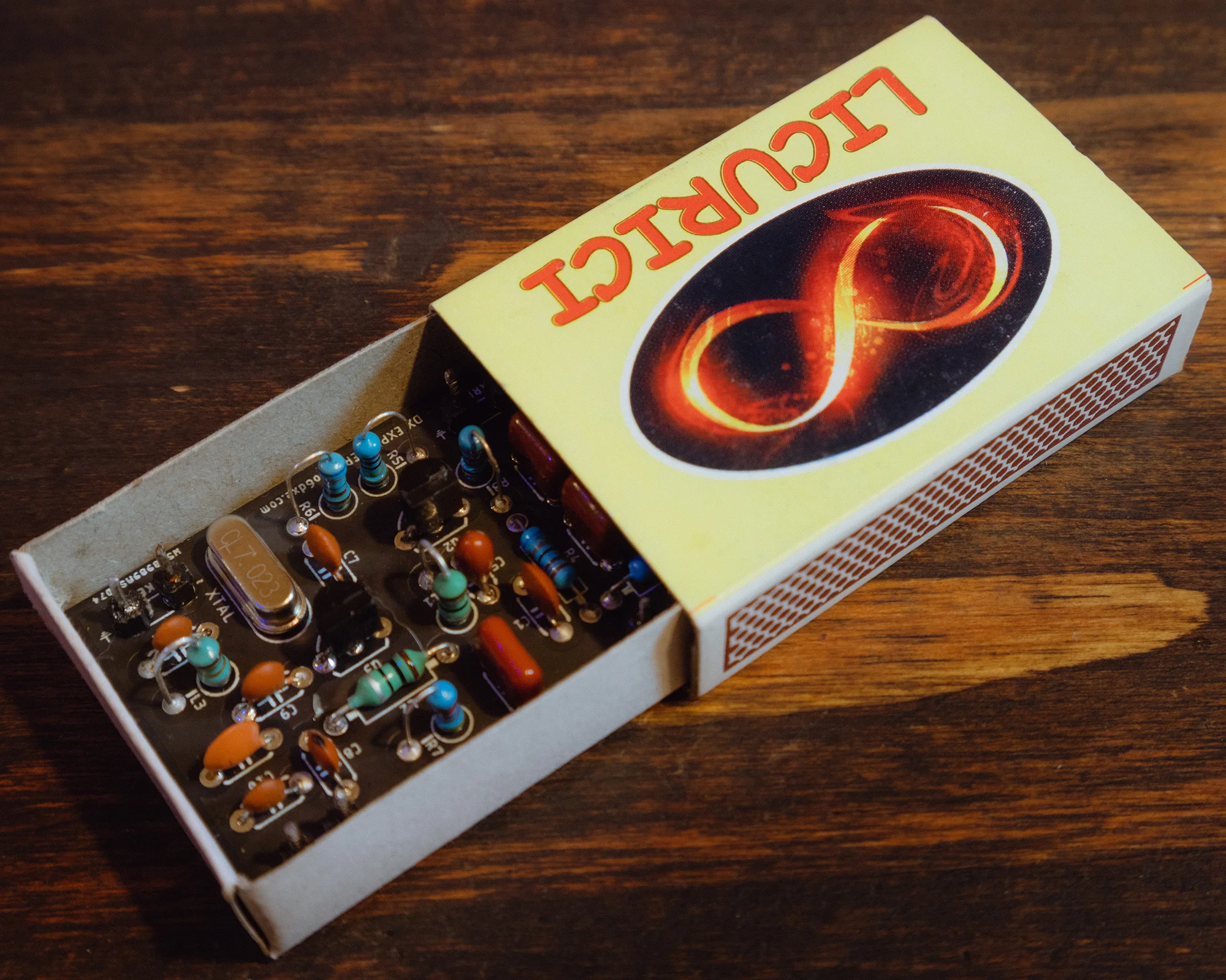
Matchbox Transceiver
Before I end the article here you have a few tips, especially if you decide to build it from scratch. In the schematic you have some values of the components for a “standard” version as the project it’s available as assembled version from PCB Way. If you decide to build it from scratch you may want to experiment with a few values to get the best out of the transceiver. Here you have a list of modifications you may want to try and what effect they have on the transceiver.
- R6 – Lowering the value will help you hear more and also it will increase the offset frequency. Keep the value of this one over 4.7K though.
- C7 – This one will help you adjust the TX frequency on the exact frequency written on the crystal. This will also help you adjust the frequency offset on receive.
- C8 – By lowering or increasing the value you may get a little more power output. In some cases for the 40m band 33pF may give you a few more mW of output power.
- C9 – The value of the output capacitor will also increase the power output. With 470pF I seem to have decent results. You may want to try 330pF, 390pF as well. This may give you some more mW as well. Just make sure you do not have chirp and the transistor it’s not heating up more than it already does. Also keep an eye on the harmonics so you will still have a clean signal.
- C3 and C4 – Lowering the value of these two to 6.8nF or 4.7nF will raise the center frequency of the filter. 6.8nF usually resonates around 800Hz while 4.7nF will resonate around 1kHz. I also used 22nF but the resonant frequency was too low around 400Hz.
- R3 – This one will also influence the resonant frequency of the filter but also how wide the filter is. If you lower the value down to 6.8K the center frequency will raise above 700 – 800Hz and it will also have a smaller bandwidth. By increasing the value to 18K the center frequency will be lower but also the bandwith will be larger.
- C11 – Adjust the value until you have the best power output and the lowest 2nd harmonic. Usually I use 150pF for this one, but I had better results in my version with only 68pF.
Please remember I am not an expert and I do not calculate things. Usually I just play around with components values until I am happy with the results. All I wrote in the article are conclusions of what I discovered while playing around with the circuit. All these “tips” are also valid for both versions of the Pititico transceivers since the schematics are very similar. So… will you dare to build a spy matchbox transceiver ? If you do then I am wishing you good luck and who knows ? Maybe sometime we will be able to do a QSO from “spy to spy” ( hi ).
73, YO6DXE

Haré una pruebas con el transceptor 👌
Me encantaría, pero no me sé bien el código. Sin embargo, tengo un amigo que vendrá a visitarme pronto y me hará una prueba la grabaré. De hecho, yo también le hice una y tiene algunos contactos registrados en ella. Realmente necesito aprender el código.
73, YO6DXE.