
Do you enjoy the content ? DONATE with PayPal to support me !
Get $5 of NEW USER FREE CREDIT using PCBWay. Full feature custom PCB prototype services, PCB assembly, SMD stencils, CNC / 3D Printing.
Introduction
The Pititico CW transceiver was originaly designed by PY2OHH. One of the smallest and simplest transceivers designed around a single 2N2222 transistor. With only a handful of components and a power output of 550mW @ 12V or 350mW @ 9V. A great project for beginners in building amateur radio transceivers. This is not exactly the original schematic that Miguel designed, as it has little improvements to overcome some issues. I found the original article published by Miguel a few years back and I loved the simplicity. In the video above you have a modified version I built. I would recommend you to also read his article as he has many notes I did not mentioned here. In this article you have the updated 2025 version.
The Schematic
The Pititico CW transceiver has a consumption of only 1.5mA in RX. In transmission, the circuit works as a low-power oscillator, capable of reaching 1W and currents of 100mA ( remember that the 2N2222 is for 80mA ). The transistor handles this current well in CW, but don’t keep the key activated for too long as the transistor will burn out. Another problem is operating without an antenna or a dummy load, the transistor will burn out.
Down below you have the original design published by Miguel in his article. To listen to the audio output, you should use a telephone speaker as Miguel recommended. It didn’t work for me, maybe I used the wrong speaker. Even better is a high gain audio amplifier. I’m using an LM386 amplifier set to the highest gain possible. It will not work with high impedance headphones.
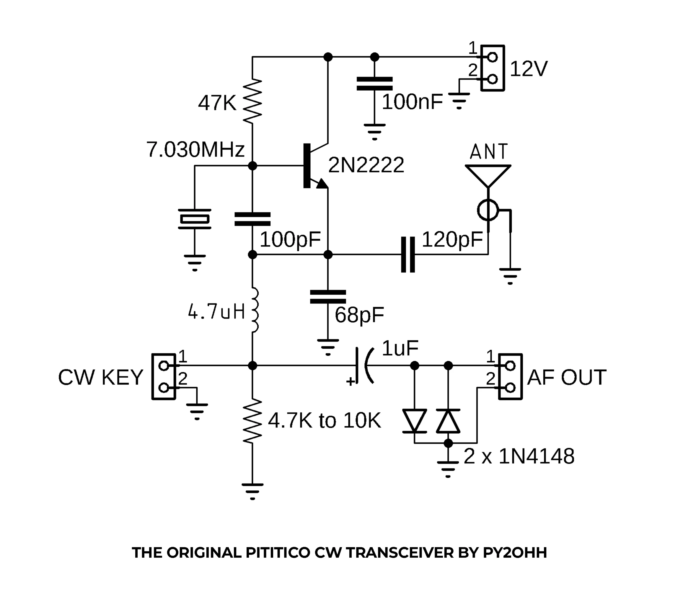
Pititico CW Transceiver Schematic By PY2OHH
The new schematic down bellow was slightly modified from the original. I would recommend 9V with 350mW as the transistor doesn’t heat up so much. C3 allows you to tune the transceiver slightly. I added this one so I can tune it exactly on 7.030MHz. CX it’s an empty spot for optional frequency offset adjustments. More on this in a little.
L2 and C4 were added to minimize the strong AM broadcast band interferences. On YouTube I also have other various versions with more or less modifications. This latest update offered me the best results so far. Miguel used it with a telephone speaker as audio output. Since that didn’t worked for me, am I now using it with an external LM386 Audio Amplifier. For convenience I also designed Pititico 2 CW Transceiver. That one has the audio amplifier incorporated.
If you take a look at the Minimalist CW Transmitter, you will realize that the Pititico evolved somehow from that simple transmitter circuit. One more note on the 1N4148 diodes he used in the original schematic to minimize the key click in the headphones on transmit. I removed those and replaced the 1uF capacitor with a 100nF. The effect was almost identical as using the diodes. The occasional buzzing sound from the electrical appliances was also minimized this way. Down bellow you have the updated schematic that I currently use.
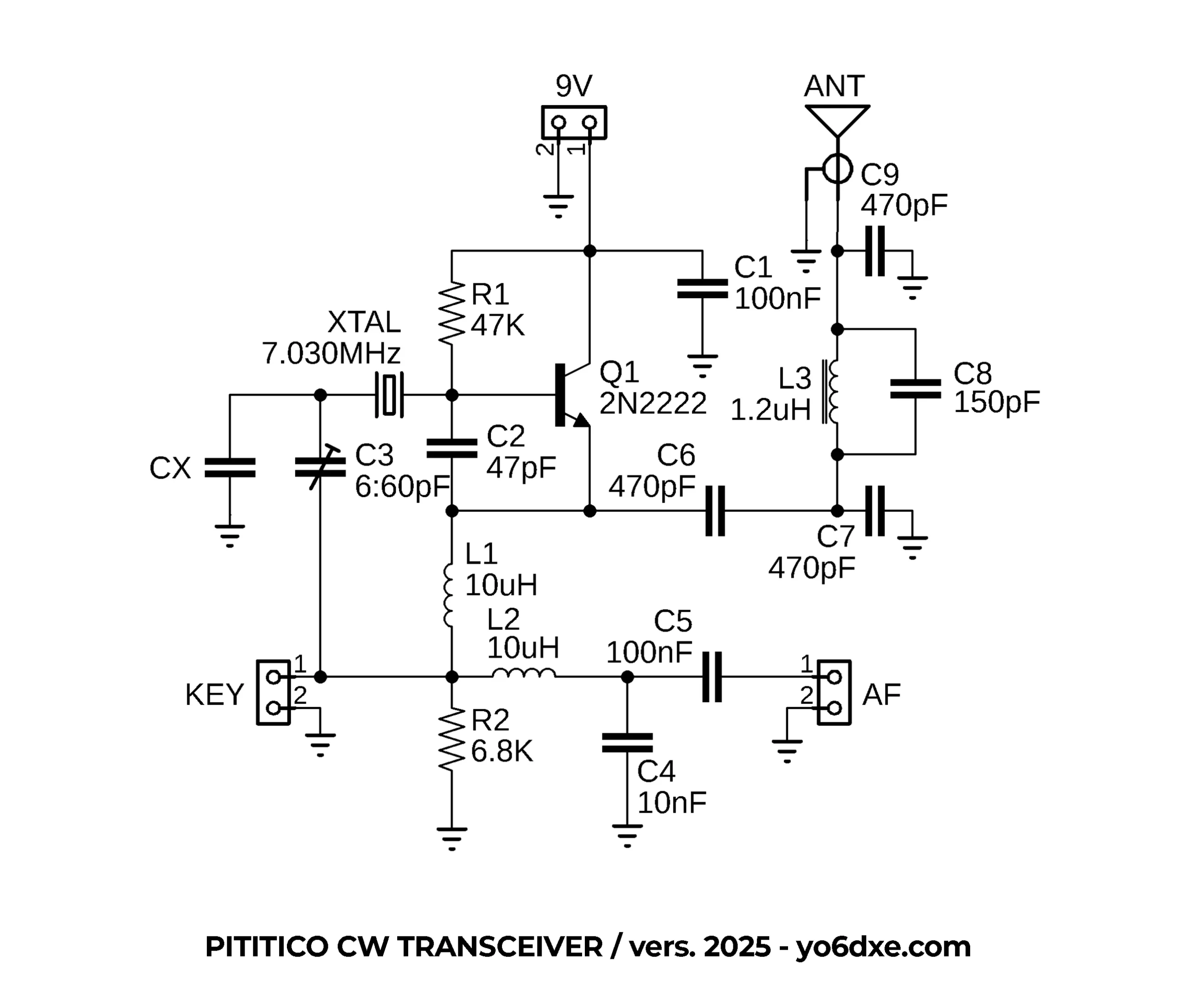
Pititico CW Transceiver Schematic By YO6DXE
Some details on R2 now. The value in the original schematic from Miguel is 4.7K. The value of this resistor will set the level of the oscillator going on air. Miguel also tested a 2.2K resistor but he could hear the Pititico in a web SDR. For that reason the value was set to 4.7K. For safety you can use 10K. This doesn’t seem to affect the sensitivity on reception. But if you use 4.7K you will hear a little more around the frequency you are transmitting on. With the 10K resistor you only hear those transmitting on the same frequency you are on. When I was doing the latest updates to the PCB boards I also noticed that the value of the resistor will also influence the RX frequency offset. With Miguel’s 4.7K resistor there is almost no frequency offset. That is the reason he used the 68pF capacitor from the emitter of the transistor to ground.
If we use the 6.8K for R2 and with the help of the trimmer capacitor C3 we adjust the TX frequency to 7.030MHz, the frequency offset it’s 800Hz. Let’s assume you want to use 10K for R2. The frequency offset in this case it’s a little too much, around 1300Hz. In case you do want to use R2 10K, I added the space for the fixed capacitor CX. With a value of 68pF in my tests, I managed to lower the offset back to 800Hz. So here are my conclusions with the resistor R2 at 6.8K. All you have to do is to adjust C3 until the transceiver will transmit on 7.030MHz and there is no other adjustment needed. If you would use 8K instead, the frequency offset should be around 1000Hz. To bring back that offset down to 800Hz, you would have to use something around 22pF to 47pF for CX.
So as you can tell the transceiver it’s pretty easy to set up. Do not use a variable capacitor for C3. It’s not meant as a VXO. The oscillator will always stay on the same frequency ( around 7.029,20MHz with the 6.8K resistor ), no matter on what TX frequency you adjust the crystal. C3 it’s there only to adjust the transceiver’s TX frequency to exactly 7.030MHz. This frequency offset thing gave me lot’s of headaches for a long time until I had it figured out. Since the circuit it’s so simple, every little change in the circuit seems to affect another part of the circuit. In the older versions if you watch the videos, I used a trimmer capacitor for CX. Since it was not needed with R2 at 6.8K I decided to get rid of it to minimize the parts count.
Performance
With a simple TO-92 2N2222 you will get about 550mW output power. I am sure that with a better transistor you may be able to squeeze a little bit more power. At some point I used a TO-18 metal can 2N2222A transistor since the plastic TO-92 one it’s getting quite hot sometimes. I was not so happy with the power output of the TO-18, so I returned to the original TO-92 version. I usually power it with 9V instead of 12V so the transistor doesn’t heat up as much. If using a 2N2222 with a good Beta, you can reach 700mW powered @ 12V.
Even with 350mW in CW you can still do contacts all over Europe from Romania. Another great thing is that it doesn’t have any chirp. It sounds great and has a beautiful tone, so you can start doing QSO’s in no time. I replaced L1 with a 10uH axial inductor because I had better results with this value. The only down side is the receive sensitivity. It doesn’t seem to be that great, but you will hear stronger signals pretty good. I generated a signal with my TinySA and around -78dB I could barely hear the signal. Don’t expect much in the days with poor propagation conditions.
The PCB Board
Using the toner transfer method, you can make a PCB board in less than 10 minutes. I started to find this a little annoying as they don’t always come out right from the first try. So now I prefer to order the PCB boards from PCBWay. Optionally you can build it Manhattan style as well.
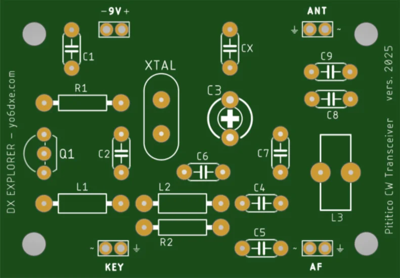
Pititico CW Transceiver PCB Board
Older Versions
Here you have the second version I built. The first one did not had a low pass filter at all. I followed the original schematic. I also liked the original design as well but I still had some issues I wanted to fix.
In this video you have the third version. I tried improving the filtering and to get rid of the AM broadcast band with the little knowledge I had when I built it. Of course the 2025 version I am using today performs way better.
On the third version I built, I moved the crystal on the top panel so I can change the crystal for other ( 40m band ) frequencies. Now this transceiver belongs to my friend YO6TJJ. More like a nice memory between friends.
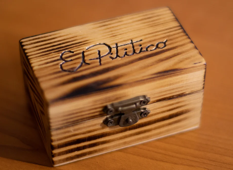
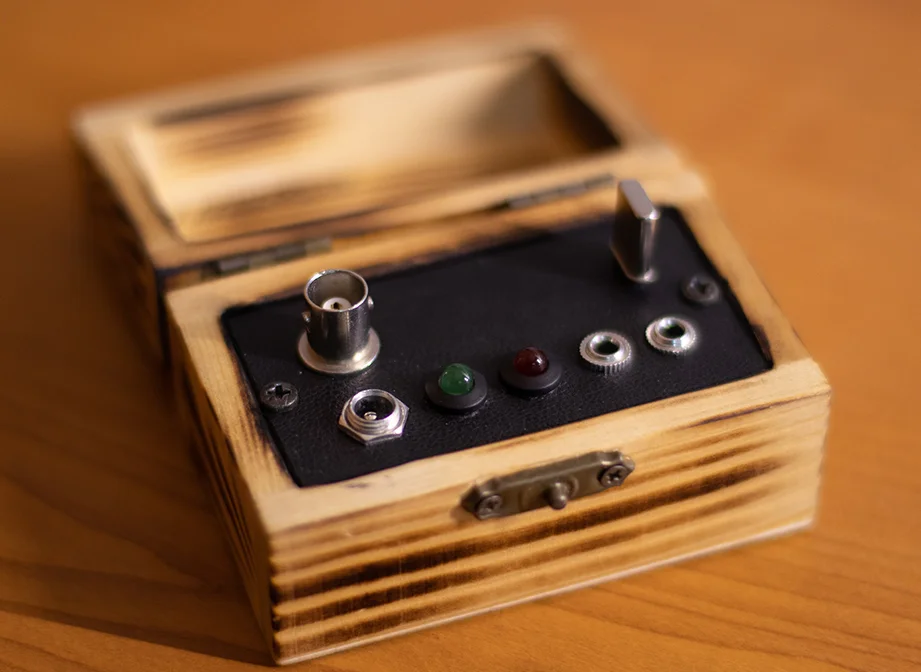
The Final Version
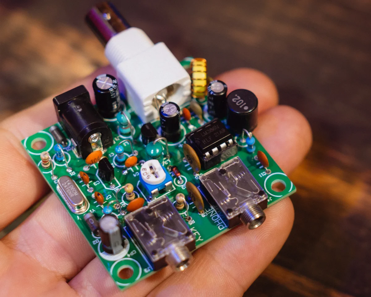
In the photo you see the blue connectors. I placed those just to avoid soldering and unsoldering wires while making tests. Normally I use small pins. The final assembled version also uses those pins, not the connectors. The space on the PCB board is a little tight for the connectors. Here you can also see the trimmer capacitor I used to have instead of the empty space for CX.
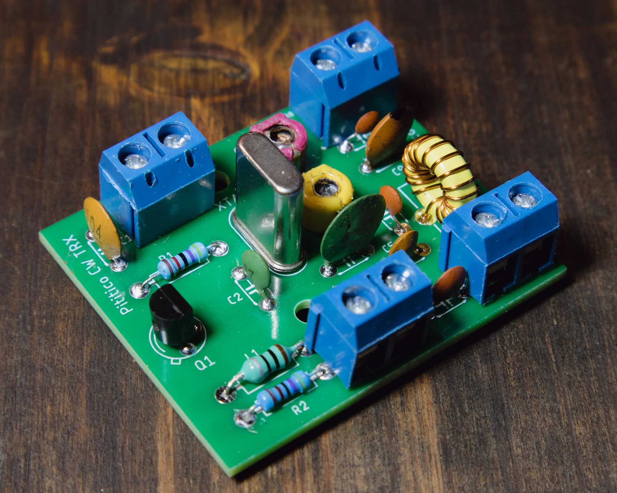
Pititico CW Transceiver
The Low Pass Filter
The inductor L3 it’s recommended to be made on a T37-6 toroid. It has 17 turns of 0.4mm enameled copper wire. I measured 1.2uH when I tested mine out of curiosity. The low pass filter it’s a modified Pi-Network filter. I got the details of the filter for various bands from the Minimalist QRP Book. The details where in the Tiny Tornado CW Transceiver ( a version of the Pixie transceiver ) designed by KA8MAV. The filter it’s not perfect, but it’s way better than the standard Pi-Network low pass filter used in the Pixie transceiver kits. If you have the expected power output, I don’t think there will be any adjustments necessary to the filter. You can adjust a little the distance between the turns on the toroid to see if you can get better results.
I did not used a standard axial 1uH inductor as in the Pixie kits because I get way better results using the toroid version. This is valid both for the suppression of the harmonics, but also the power output of the little transceiver. If you do a scratch build, feel free to replace the filter with a better one if you want. I used the Pi-Network low pass filter because I wanted to keep the components count to a minimum. From a practical standpoint at this power level, the harmonics level should not cause any issue. If an antenna tuner is used, it will likely reduce the harmonics level even more.
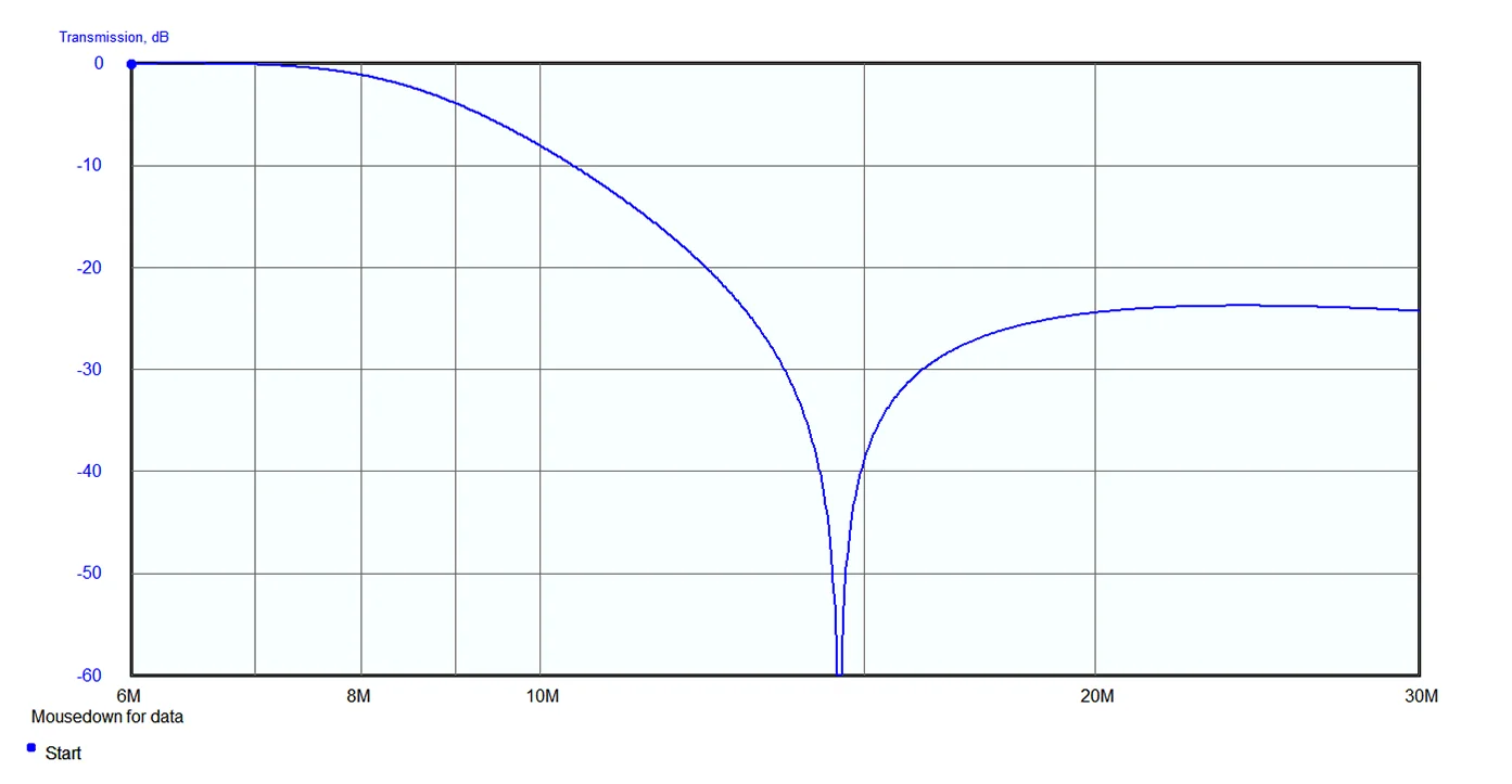
40m Band Pass Filter Simulation
Ron WB5DYG built the older Pititico 2 CW Transceiver and while playing around he also made some modifications. You may want to have a look at his video, or you can download his PDF notes. You may find various other ways to further improve this simple design. Some of his notes are also valid for this simple version of the transceiver.
I am wishing you good luck building the Pititico CW Transceiver. It’s really tiny and easy to build by beginners. Feel free to experiment using other transistors as well. Also by changing the value of C6, you may be able to increase the power output. I had the best results with C6 having a value of 470pF. Just keep an eye on the transistor so it will not overheat.
If you keep the key pressed for about ten seconds and the transceiver it’s not stable in frequency, chances are the transistor it’s overheating. Also if there is any chirp, that is usually from the same reason. David ( DL1DN ) from QRP Lifestyle built a modified version for the 10m band, so feel free to do modifications for other bands as well. I hope you like this project as much as I do. Now all I have to do is to learn the Morse code and get on air using CW on this tiny QRP transceiver that I absolutely love. I just need to find the right telephone speaker to really use it as a one transistor transceiver. Do you know how to calculate or measure the audio output impedance for this circuit ?
73, YO6DXE