

Do you enjoy the content ? DONATE with PayPal to support me !
Get $5 of NEW USER FREE CREDIT using PCBWay. Full feature custom PCB prototype services, PCB assembly, SMD stencils, CNC / 3D Printing.
Introduction
Sputnik regenerative receiver has decent receiving capabilities. It’s a simple regenerative receiver for SSB, CW, AM and FM. It was designed for the 40m amateur radio band. It can be adapted to other HF bands as well. It works great on 80m, 40m and 20m as tested by me. It was designed for beginners to help them improve their knowledge in building radio receivers.
A version of this article was also published in the RADIO Magazine ( No. 4 December 2023 ), available in digital format translated in English downloadable as a PDF file.
I found the original schematic in the Romanian Tehnium magazine. That one had no buffer stage on the antenna side and the audio amplifier was made with two germanium transistors. The audio output was extremely low. At the time I tried to improve that circuit, I did the best I could with the limited knowledge I had at that time. And that is how Sputnik Regenerative Receiver was born.
The Schematic
If you wonder why the receiver it’s called Sputnik, the explanation is somehow simple and also funny. Because of the way the propagation works, after building the very first versions, all I’ve heard during the day time were the Russian amateur radio operators. Since I’m a fan of the vintage space era, knowing that Sputnik was the first Russian satellite launched, I decided to call the receiver the same way.
With ought any intention, for some reason it became popular around the world. Different older versions of the receiver are popular on a QRP Forum in Germany and the SolderSmoke Blog. California QRP Club also asked the permission to use it for a kit build, with slight modifications by John Sutter K6JDS. It had some nice words from Peter Parker VK3YE on his Facebook Page. I have loads of emails and photos from the subscribers to the YouTube channel that also built the Sputnik Regenerative Receiver.
Down bellow you have the latest schematic design ( vers. 2025 ). This is the final update as I will no longer make any updates. I wanted a receiver as small and as simple as possible, but with decent performance. To keep it simple and small I did not used an audio preamplifier, but the audio output is good enough for a small speaker or headphones. If outdoors, the speaker it’s not so loud so headphones are a much better choice.

Sputnik Regenerative Receiver Schematic
I decided not to use a voltage regulator, as it doesn’t help much when using batteries. If the voltage drops under 12v, the LM386 IC will end up creating that ugly “motorboat” sound. To improve stability in frequency I used D4 – 9V1 Zener diode. If you want to improve the frequency drift even more, you can use a variable capacitor instead of the diode tuning. This will improve the stability of the receiver even more. I would recommend a variable capacitor with some sort of reduction drive.
I also decided to get rid of all sorts of filters that I used in some of the older versions. There is no more bandpass filter on the input. I tried to get rid of the AM broadcast band interferences by testing the audio amplifier in all sort of configurations. There is no more CW audio filter either. Instead I opted for a solution that makes both CW and SSB signals sound good. This way the schematic is very much simplified.
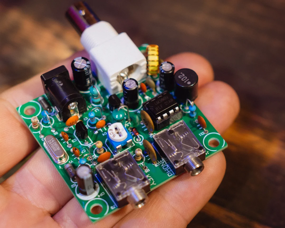
The PCB Board
Using the toner transfer method, you can make a PCB board in less than 10 minutes. I started to find this a little annoying as they don’t always come out right from the first try. So now I prefer to order the PCB boards from PCBWay. Optionally you can build it Manhattan style as well.
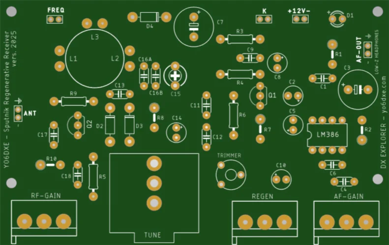
Sputnik Regenerative Receiver PCB Board
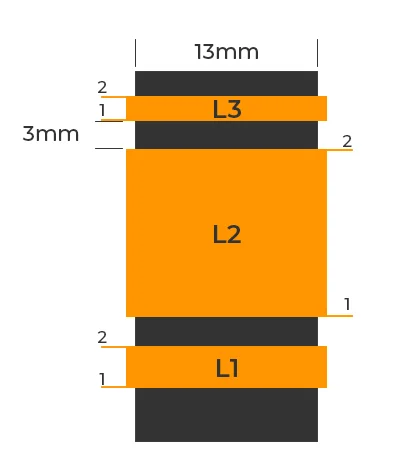
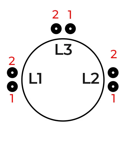
RF Coil Design
To calculate inductances if you want to use a toroid, I would recommend toroids.info website. If you decide to build the coil on a PVC pipe as I prefer, then you can use Coil32 Software to calculate the desired inductance and also the resonant frequency. There should be a balance between the LC circuit capacitors and the inductance of the coil to have the receiver very stable in frequency. If you go to high with the inductance and too low with the capacitance, the receiver will drift a lot.
Even though a higher inductance allowed me to tune the entire 300Hz on the 80m band with only two 1N4001 diodes. Using a varactor diode will help you have more capacitance swing. That will allow you to have smaller inductances in the coils and more stability in frequency. It’s up to you to experiment.
Down bellow you have the RF coil details for the 40m amateur radio band. You can also calculate it for other HF bands as well. I tested it from 80m up to 20m and it works great. When I started playing around with receivers schematics, I did not know how to calculate the circuits to resonate on the frequencies I wanted. I learned the hard way and at first I discovered how to do it by trial on error.
L3 has 3 turns of 0.4mm enameled copper for both versions of the coil. If you use a frequency counter that has a preamplifier, sometimes even one single turn may be enough. More than 3 turns unfortunately seems to introduce noise in the receiver. Noise generated by the frequency counter.
Sputnik RF Coil Details PVC Version
| BAND | L1 | L2 | C16 |
|---|---|---|---|
|
40m |
8 turns – 0.4mm |
24 turns – 0.4mm ( 6.4uH ) |
100pF |
Sputnik RF Coil Details Toroid Version
| BAND | L1 | L2 | C16 |
|---|---|---|---|
|
40m |
3 turns – 0.4mm |
32 turns – 0.4mm ( 6.4uH ) |
100pF |
RF Attenuator
The RF attenuator will help you to adjust the signal level entering the receiver. It will also stop the RF generated by the regeneration stage of the receiver leak back into the antenna. This RF attenuator stage was borrowed from another regenerative receiver designed by N1TEV ( SK ). This is not an RF preamplifier as many people think. It does amplify the signal, but only a little. It’s nothing but a buffer stage.
Regenerative Receiver Stage
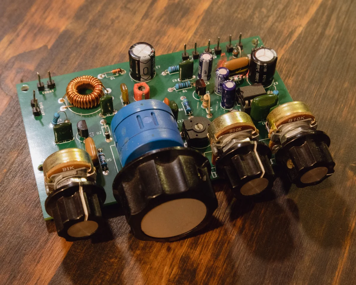
This is a simple regenerative stage. The level of regeneration it’s adjusted using the 10K regeneration potentiometer. I wanted to bring the receiver to a stage where the regeneration control it’s really smooth and easy to use. It can also be used as fine tuning. Some people like using a 10K multiturn potentiometer instead.
For a good stability in frequency C11, C12 C13 and C16 should be the NP0 type capacitors. If you have too much capacitance, or not enough and you can’t get the receiver into the desired band, you can either increase or decrease the value of C16. For C16 you have two spots on the PCB board ( A and B ). This is in case you want to split the value of the capacitor in two. Using two 47pF capacitors instead of a single 100pF capacitor, will help a little in frequency stability.
With the help of the trimmer capacitor C15, set the receiver in the higher part of the band ( ex 7.2MHZ ), with the multi turn potentiometer all the way at the end. Then with the help of the 10K trimmer resistor, set the receiver at the beginning of the band ( ex 7.00MHz ), with the multi turn potentiometer all the way at the beginning. Or if you want you can simply set the receiver just for the CW or the SSB part of the band.
Diode Tuning
The diode tuning was used in the design to replace the variable capacitor. These days is hard to get your hands on a good variable capacitor. If you do have a variable capacitor, replace the diode tuning with the variable capacitor as the receiver is more stable and there is no frequency drift when the battery goes low. With the two 1N4001 diodes I can cover the entire 40m band. One of the reasons I used regular diodes instead of varactor diodes, is that they are really easy to find. If you want you can replace them with BB405 or similar.
The diode tuning stage it’s formed from the multi turn 10K potentiometer, the 10K trimmer resistor, C13, C14, D2, D3, and R8. If you want to replace the diode tuning with a variable capacitor, you can connect it in the spot designed for C13. Replace D2 with a jumper wire. The value of the variable capacitor should be at least 20pF.
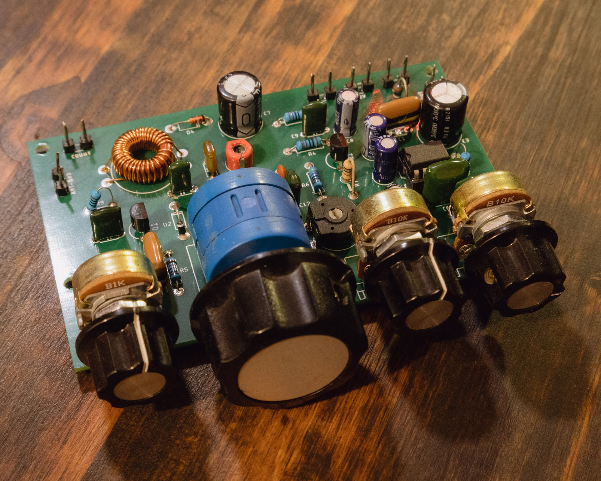
Sputnik Regenerative Receiver
Audio Amplifier
Initially the intention was to use an audio amplifier based on transistors only. The LM386 amplifier can be anytime replaced with another audio stage if you want to. I wanted to use the LM386 because of the simplicity and because the IC it’s easy to find. The receiver presented here does not include an audio preamplifier, but the audio level on the output is strong enough to power regular headphones. Is also good enough for a speaker if listening in a quiet room. Not loud enough if listening outdoors. Try using a larger speaker as it gives a better sound. I honestly prefer to use an external amplified speaker most of the time when not using headphones.
Power Input
This is a simple stage powered by 12v for the LM386 audio amplifier and 9.1v for the regenerative receiver stage, RF preamplifier and the diode tuning stage. R3 it’s used to lower the voltage to about 9.5V. C7 is used to filter the voltage for the 9.1v stages. The voltage is slightly stabilized by the Zener Diode D4 to 9V1.
More About The Receiver
The receiver in the video was built based on the first schematic designs I tested, trying all sort of configurations. Here in this video you have a little more info and details on the receiver.
The Original Video
This was the first modified version of the receiver. At the same time, my very first video on the YouTube channel. I am happy that I learned a lot thanks to this receiver and happy the way it turned out.
Building Tips
If you decide to build the receiver Manhattan style or dead bug style, try to keep the connections between components as short as possible. Well built with attention to detail it can end up as a really nice receiver. I tried keeping it simple for beginners. I still have ideas of improving this design, but I will simply leave it as it is. I already spent two years playing with the schematic until I was happy with the results ( hi ). It was also designed as a portable receiver with a minimum battery consumption. Using a variable capacitor instead of diode tuning ( one with a reduction drive ), can make the receiver even more stable. I hope you like it and you have success in building it. Feel free to email me if you have issues building it. I will try my best to answer to you all.
73, YO6DXE

Hi YO6DXE,
I have built this reciever and it works phenomenally. I have made a version of it tuned to the 80-meter band by changing the PVC coil to one with 11 turns on L1, and 47 turns on L2 (I also added a 30pf capacitor alongside the other 2 47pf ceramic caps). I was wondering if you have made any tests with this receiver on the 20-meter band as well. If so, what turn ratio should I use? And should there be any changes to the capacitance as well?
I plan on building a version of this receiver using DIP switches to switch between the 80, 40, and 20 meter bands, respectively.
72
– Logan A.
Hi Logan. Yes I built a 20m version as well at some point. It was working really nice. I do not remember the number of turns for the RF coil and I think I only tested the toroid version, but for sure it worked really nice. I will try to look through some old notes and if I find the details I will get back to you.
73, YO6DXE.
Salut Ciprian
Citeam articolul sputnik-regenerative RX. Butonul DOWNLOAD FILES descarcă documentația pentru Pititico.
Spor în toate,
Gelu Botezan, Yo5TC
Multumesc mult. Posibil sa fi copiat aiurea link-ul. Asa e cand scriu articole la 3 noaptea (hi). Am corectat… probabil o sa intru prin toate sa le verific asa ca masura de siguranta. Multumesc mult.
73, YO6DXE