
Do you enjoy the content ? DONATE with PayPal to support me !
Get $5 of NEW USER FREE CREDIT using PCBWay. Full feature custom PCB prototype services, PCB assembly, SMD stencils, CNC / 3D Printing.
Introduction
In this article we will build a simple 455kHz BFO for SSB and CW reception to use with an old shortwave AM radio that has 455kHz IF frequency. Most AM broadcast band receivers do not have a BFO, so we cannot listen to SSB or CW signals. For a shortwave listener that would like to use an old AM broadcast band receiver and listen to amateur radio operators, this BFO it’s the perfect project to build. There are many schematics online that I tried in time. At the end I picked this one because it seems stable enough and it doesn’t require too many components.
The Schematic
After many headaches trying various schematics I found, more or less complicated, I decided to something simple. Some other I tried also worked, but they had a complicated circuit, or used components harder to find. So this one it’s just a simple Colpitts oscillator using a ceramic resonator. I used this 455kHz ceramic resonator. You can also find them in many broken receivers sometimes or other electronic devices. Since this is an external BFO ( no need to place it inside a receiver ) there is an antenna output. That is nothing but a piece of wire placed close to the receiver. Sometimes it even works with no antenna at all depending on the receiver, if the BFO it’s placed close to the receiver.
Normally for a better frequency stability, we would use a voltage regulator. I decided not to use one to keep the schematic as simple as possible. Of course the reason was to keep the components count to a minimum. As it is, with a simple 9V battery it should be stable in frequency and the battery will last a long time. The power consumption is minimal. If you do have issues with the frequency stability and you think it’s caused by the voltage, feel free to use a step down power converter module. I usually use one set to 9V, together with a basic 12V power supply. This way I don’t have to buy batteries all the time.
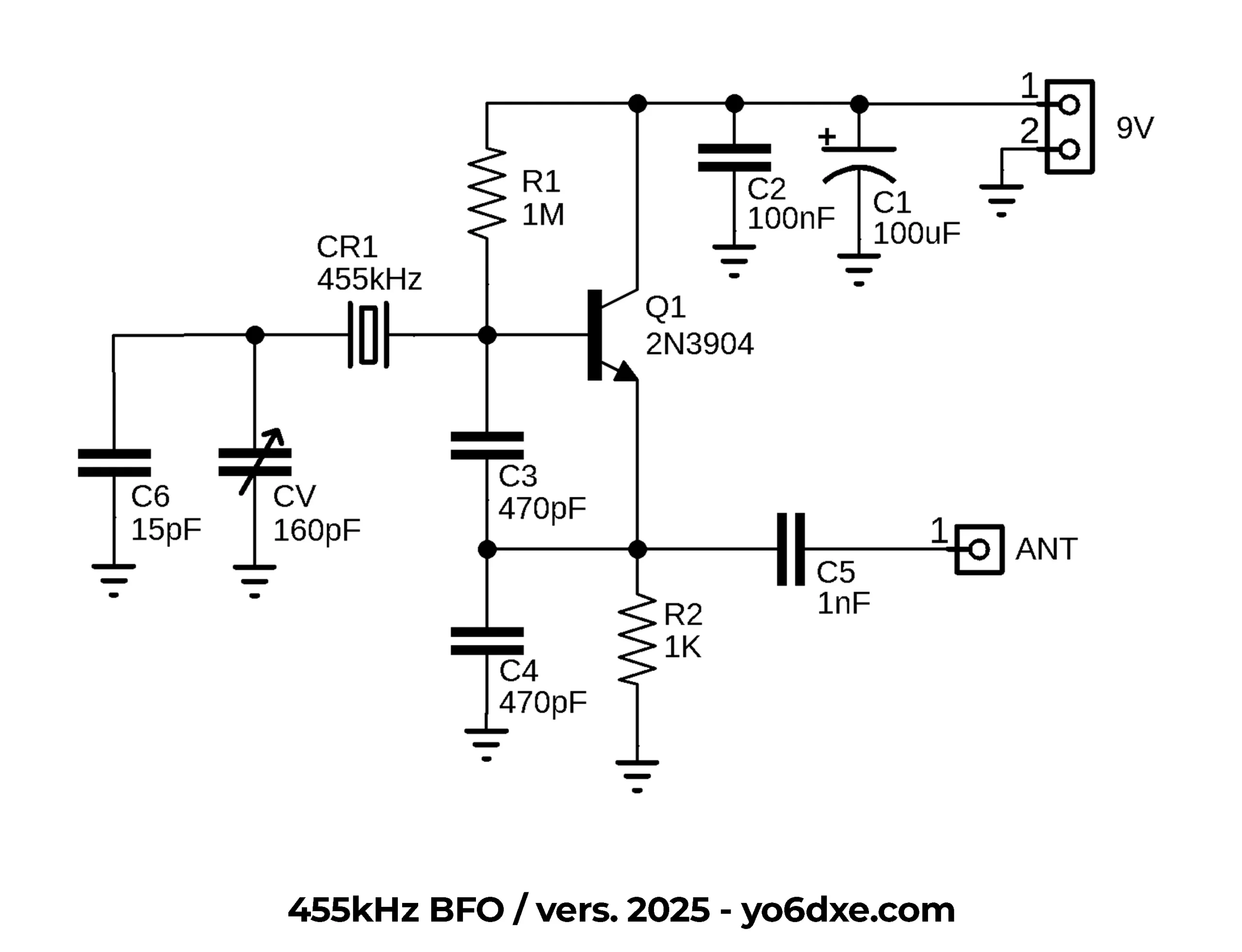
455kHz BFO Schematic
The PCB Board
You can always build it Manhattan style, but I prefer to order the PCB board from PCBWay. This way all my projects look nice and alike. I do build Manhattan style as well, but usually just as a prototype for testing, then transfer all the components on the PCB board when this one arrives.
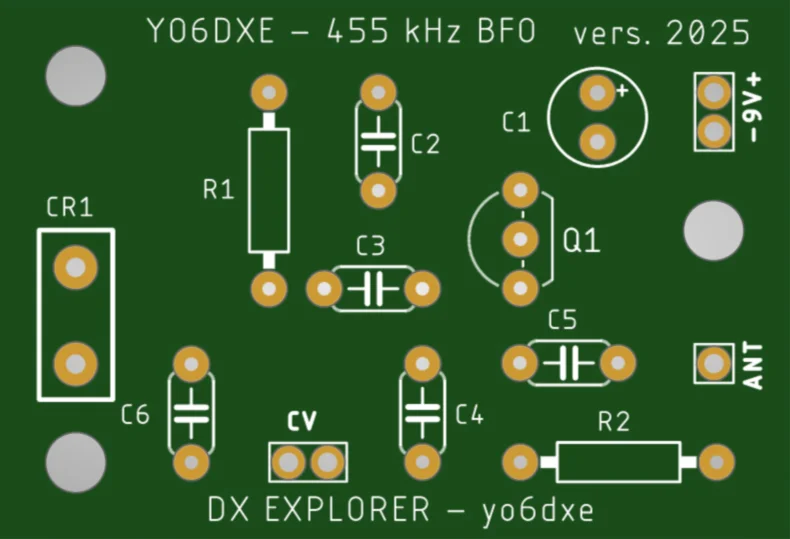
455kHz BFO PCB Board
Building The BFO
Talking about building it Manhattan style for testing purposes, here it was my prototype built on a breadboard. One advantage of the breadboard is that it allows you to change components quickly and there is no soldering involved. On more complicated circuits, it can give you headaches. Sometimes because something doesn’t make proper contact, other times because of capacitance issues and lots more. Still this is a good method to test simple circuits.

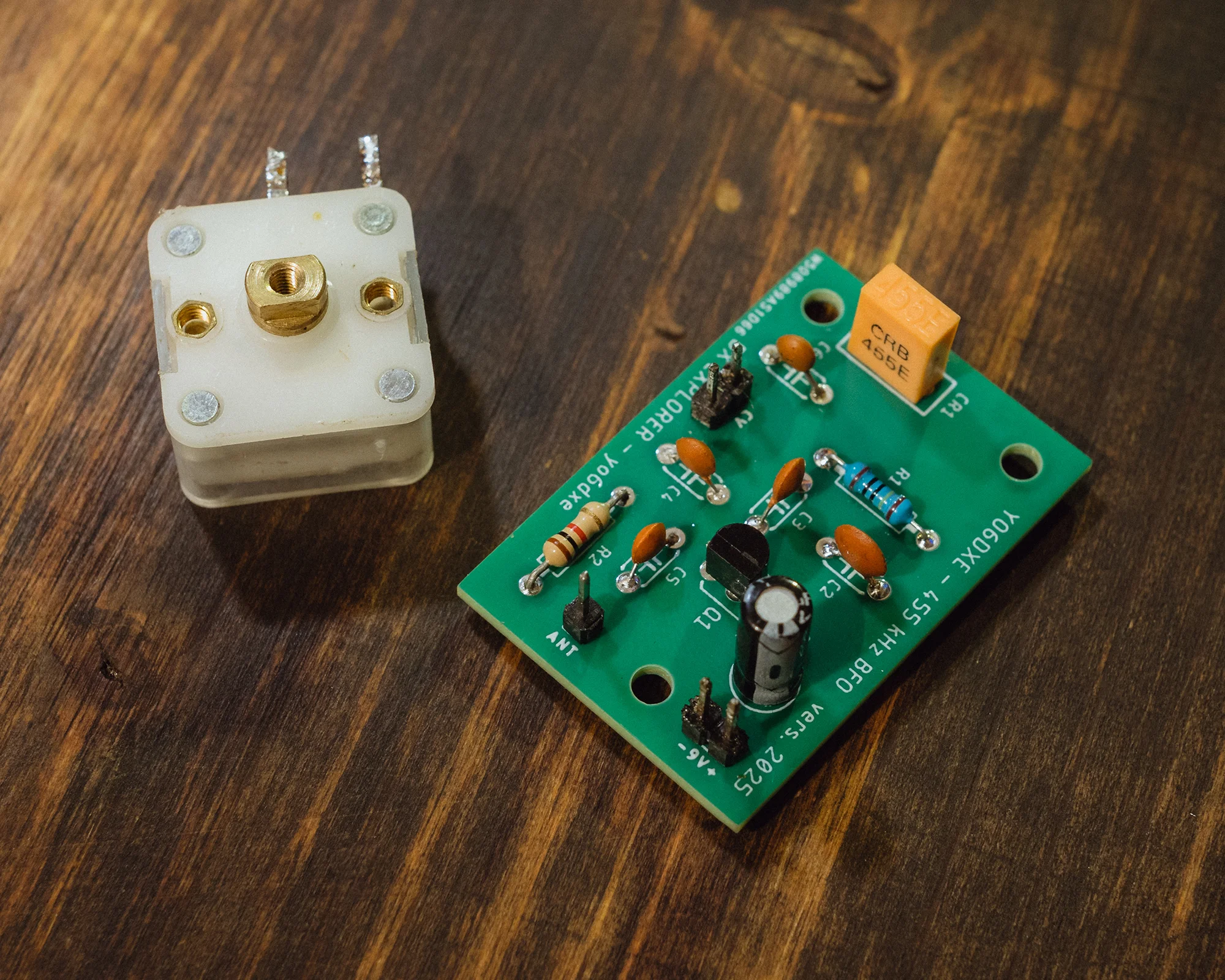

455kHz BFO From Breadboard To Final Project
As I was saying earlier, once I design the PCB board after finishing all the tests, when the PCB boards arrive I always build the final circuit this way. If I spend so much time working on homebrew projects, I would rather build something that will also last a long time. The only reason I do not like that much building Manhattan style, is that sometimes the copper boards get corroded really ugly. For this reason I prefer using properly made PCB boards. Plus that I always get 5 so it’s nice sharing the extras with friends that also want to build the same project. Sometimes I actually gift them the finished project. They turn out to be great gifts for my friends.
Here you have the video with the first tests I made with the circuit built on a breadboard. Usually for RF projects, the breadboard may not be the perfect choice. But sometimes I do have success and not so much headaches. I would recommend the Manhattan style instead when it comes to prototyping.
Useful Gear
For this built you can use a variable capacitor that you recover from some AM/FM radio receiver. Usually the ones I use have two sides, 60pF or 140pF and you can purchase them AliExpress. In the video I was also using the frequency counter to measure the frequency output of the BFO. You can find the kit available on AliExpress as well. In the video I explained that the frequency counter I used it’s not the standard kit, but a modified version. Here you have a video explaining how to modify the frequency counter kit. You will pretty much remove the crystal checker and use the components to build an RF preamplifier instead ( plus a few more extra resistors ).
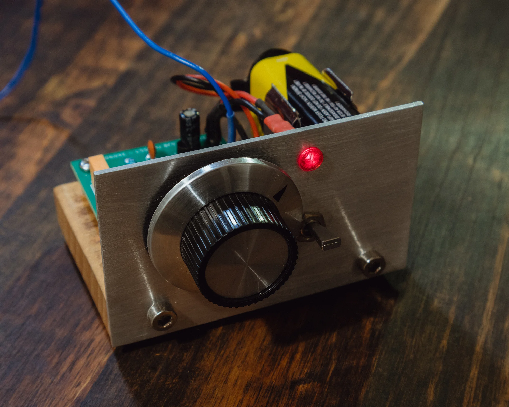
Finished 455kHz BFO Project
How To Listen To SSB And CW Signals
First of all you need to make sure that your receiver has an IF frequency of 455kHz ( many of the older ones do ). In a normal situation all you need to do is to place your BFO close to the receiver ( the wire of the BFO used an antenna ). Then try to tune into an amateur radio band and see if you can receive some CW signals in the CW portion of the band. Usually you get to hear some interruptions in the static in Morse code. Then using the variable capacitor from your BFO, you will have to adjust it to resonate exactly on 455kHz. That is when you will start hearing a proper CW signal in the receiver. Of course you can make adjustments afterwards to the tone according to your own preferences. If you have any gear that allows you to measure the output frequency of the oscillator ( BFO ), you can tune this one to 455kHz before using it with the receiver.
I hope this circuit helps and you get to enter into the world of amateur radio with just a few components and an old AM receiver. I wish I had this one when I was little. Usually I was just listening to the Morse code with no BFO. All I could hear were those interruptions in the static.
73, YO6DXE.