
Do you enjoy the content ? DONATE with PayPal to support me !
Get $5 of NEW USER FREE CREDIT using PCBWay. Full feature custom PCB prototype services, PCB assembly, SMD stencils, CNC / 3D Printing.
Introduction
In this article we will build a pocket-size VLF up-converter with NE612. Listen on VLF with any receiver that has the 30m band ( 10MHz ) and SSB or CW modes. This project emphasizes leveraging common, affordable components preparing for the Christmas SAQ transmission. VLF exploration doesn’t require expensive, specialized equipment but rather clever circuit design.
I’ll show you how to construct a portable NE612 VLF up-converter. You will have your own VLF monitoring station and start exploring the invisible world of VLF. You can also use it to listen to the submarine signals and many more interesting signals.
The Schematic
Initially I thought about building the VLF up-converter that my friend Andrei – YO6TJJ wrote about in the article published in the RADIO Magazine ( No. 1 September 2023 ). That one was originally published in the Elektuur magazine in June 1998. Unfortunately I did not all the required components in my junk box, so I decided to find a simpler version. I did a search for some more schematics and ended up modifying the project according to my needs.
I wanted to have the finished project ready for the SAQ transmission from 24th of December 2025. The only down side is that this VLF up-converter it’s using an obsolete part, the NE612 chip that is no longer manufactured. Luckily the NE612 chip it’s still available on AliExpress. I don’t think these are originals and how well they perform, but I do hope something it’s better than nothing. The NE612 chip it’s a low cost mixer that unlike a passive diodes mixer.
This one will also offer decent gain. Since my interest was to only receive signals under 80kHz, I designed the low pass filter this way. If you want to receive higher frequencies, feel free to replace L1 and L2 with 2.2mH inductors instead. I just wanted to make sure I do not get any interferences from stations above 150kHz. It performs great and I am really happy with the results so far.
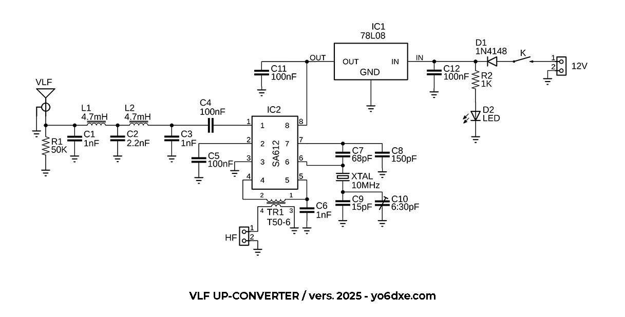
VLF Up-Converter Schematic
The VLF Up-Converter Prototype
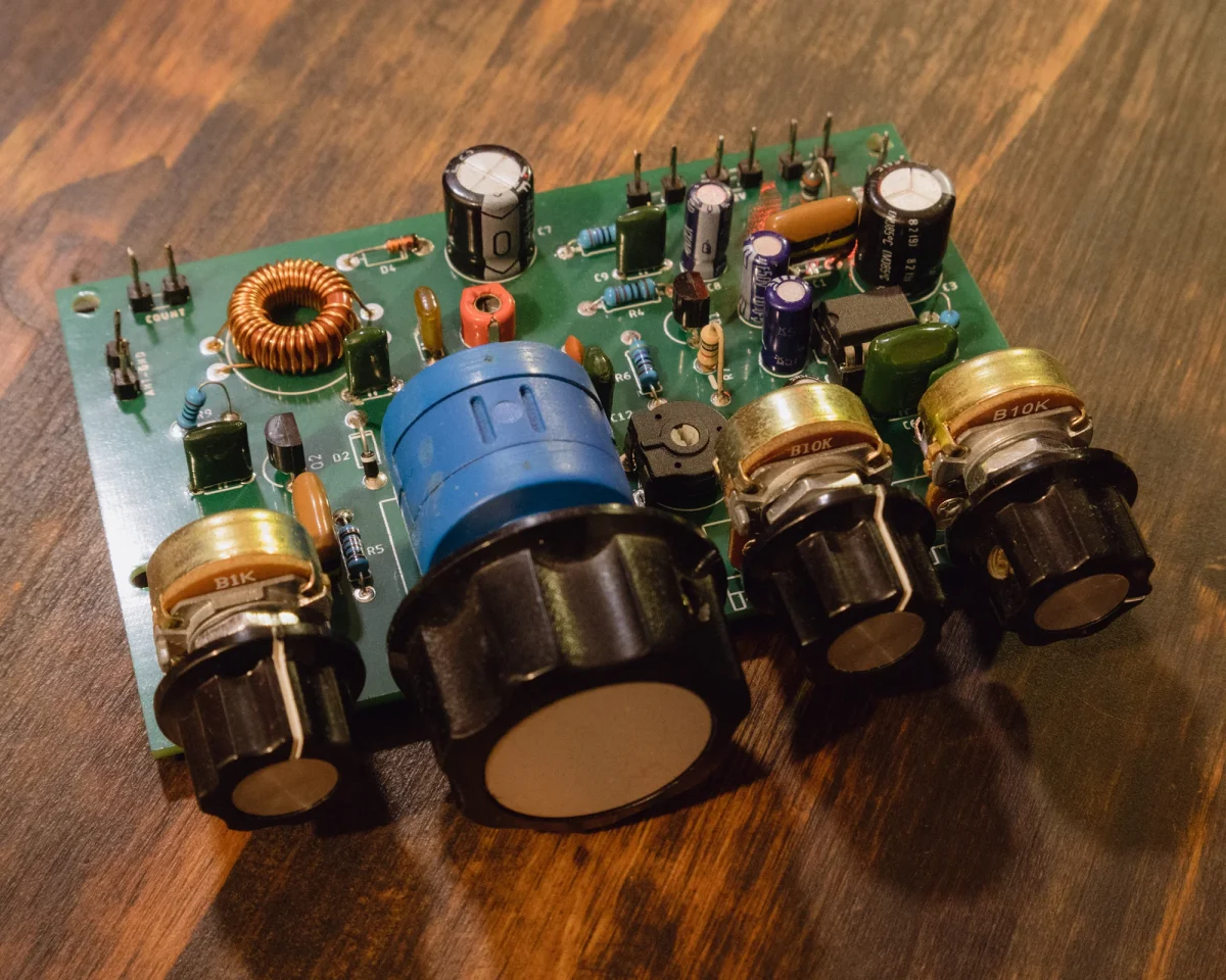
I built the first prototype of the VLF up-converter using the Manhattan style method. I wanted to test it properly and make any necessary modifications in this stage, before designing the PCB board. I seriously thought at some point to keep this version. Then I remembered how ugly the copper corrodes, so I decided to build the PCB board version instead as a final build. On the output as you can see in the schematic and the image, I used an impedance transformer. This was done to match the symmetric output of the integrated circuit to the 50 Ohm asymmetrical input of the transceiver. Since the output that goes to the transceiver was designed for 10MHz, I decided to use a T50-6 toroid. Since these are well rated for frequencies between 3 to 40MHz.
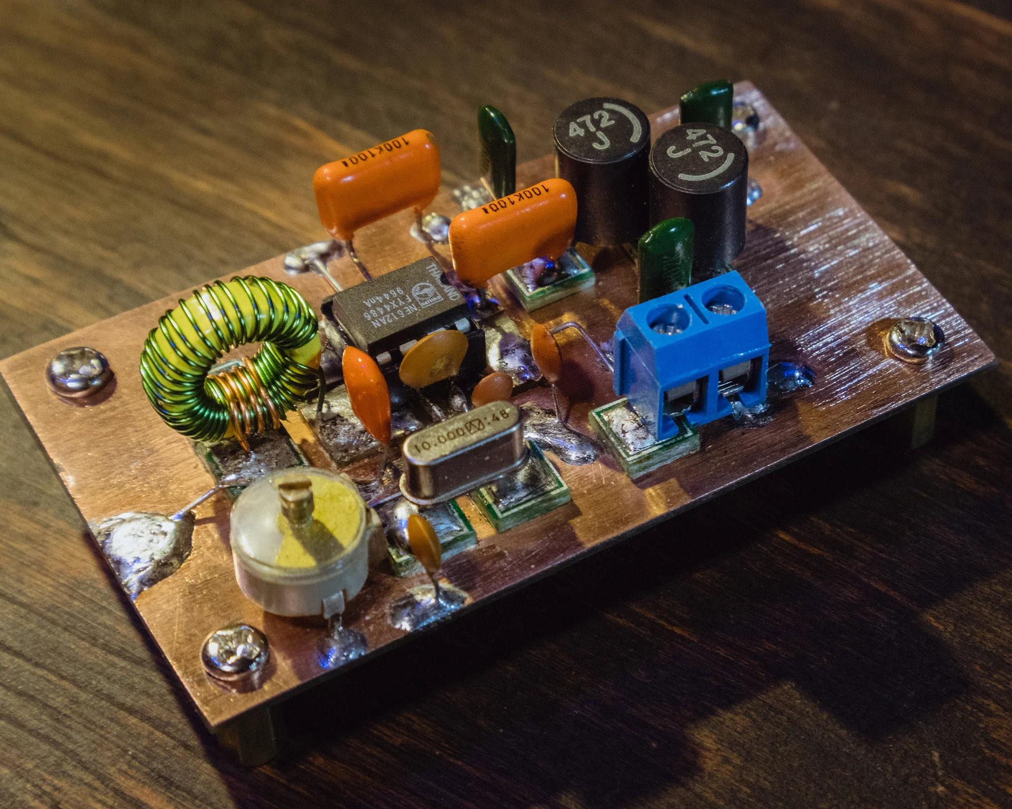
Manhattan Style VLF Up-Converter Prototype
The primary of the impedance transformer has 32 turns and the secondary has 4 turns. Both wound using 0.4mm enameled copper wire. You can use different color insulation wires to make it easier for you if you want. In the video down bellow I explained in detail how to build and position the impedance transformer on the PCB board. The resistor R1 was used to discharge any static from the antenna. The voltage stabilizer I use in my built was 6V, but you can use anything between 5V up to 9V. I prefer 8V for safety so that is what I used in the schematic. The diode D1 serves as reverse voltage protection. Just in case you connect the battery wires the wrong way.
The PCB Board
You all know that lately I prefer ordering the PCB boards from my friends at PCBWay. I like building Manhattan style, but I want to make sure that if I build something it will also last a long time. You can also order the VLF up-converter as assembled version.
Due to the fact that the NE612, NE602, SA602 or SA612 chips are no longer in stock from major suppliers, the assembled version of the VLF up-converter from PCBWay will be delivered with ought the IC. You will have install that one on your own ( not provided by PCB Way ). Instead PCBWay will only install the IC socket so you don’t have to do any soldering. I usually purchase the NE612 chip from AliExpress. For now I think I still have a few left sent by my friend Nigel – ZL1NAY three years ago.
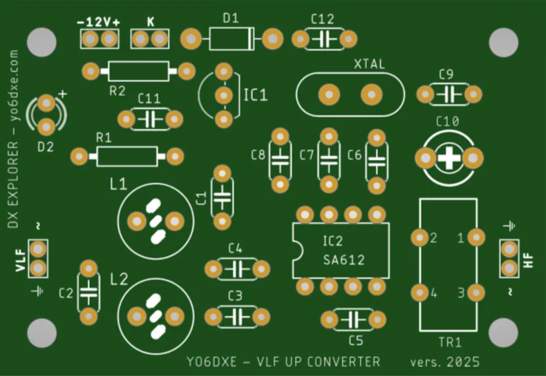
VLF Up-Converter PCB Board
Building The VLF Up-Converter
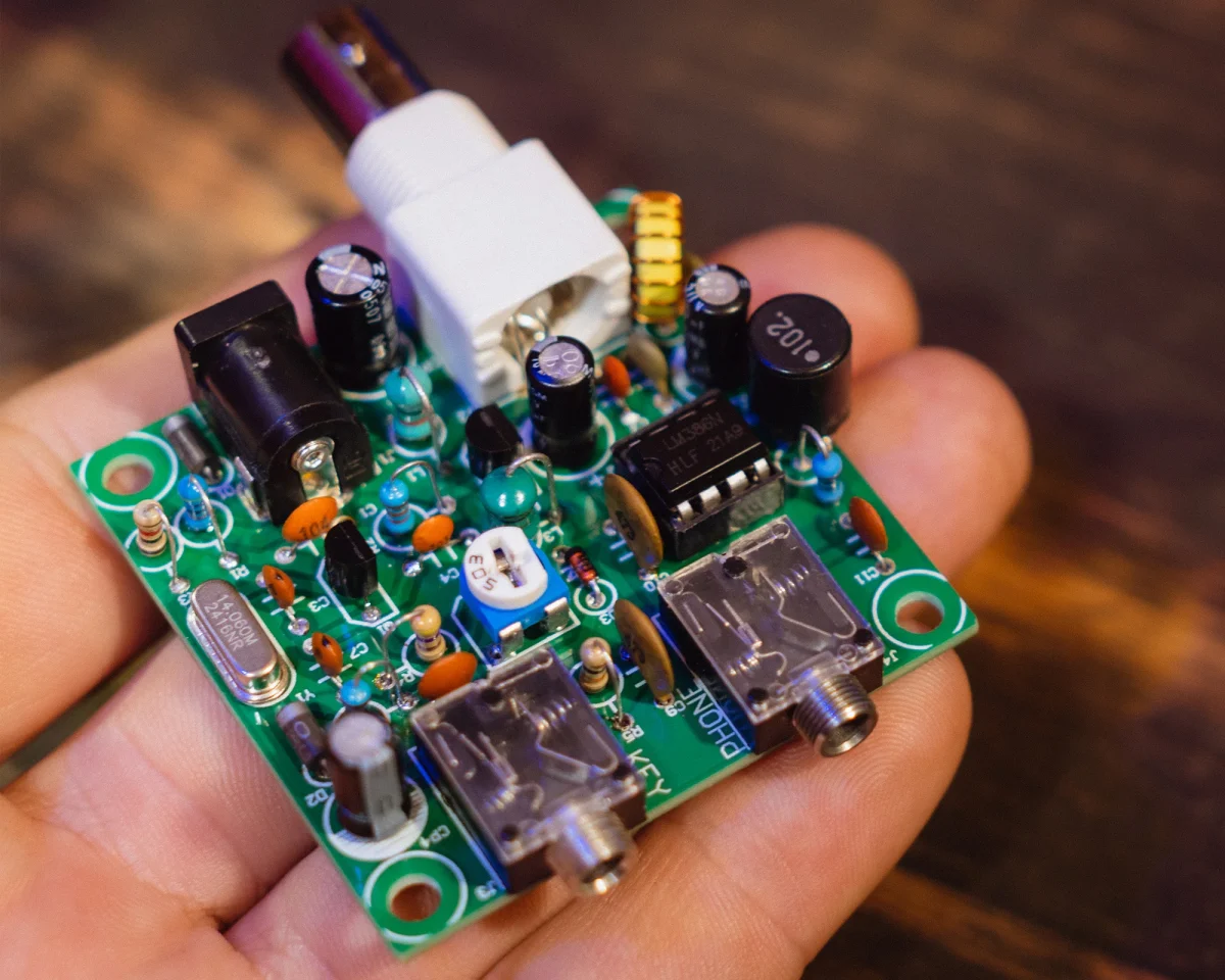
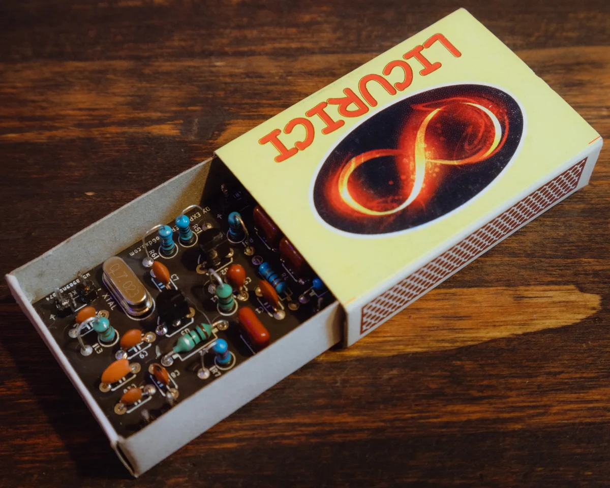
You can build it even smaller than I did and I also recommend a metallic enclosure instead of the one I made. But honestly any enclosure would do. Using a metallic enclosure you just make sure that you avoid any possible interferences. I built mine in a DIY wooden enclosure made from thin plywood. I love the wood and aluminum combination that I used for the 455kHz BFO. That it’s all I had available. For the faceplate I used a piece of aluminum sheet to give my project some sort of vintage look. That also with the help of a flame torch and some stain and oil for the wooden enclosure. It turned out really nice and I really like it.
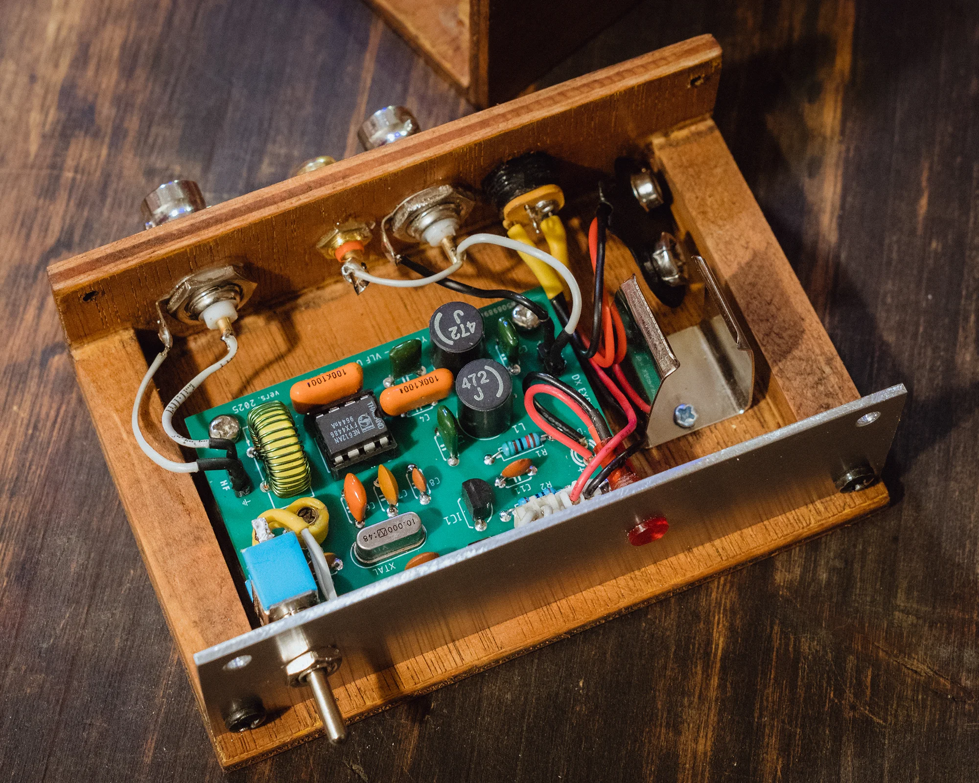
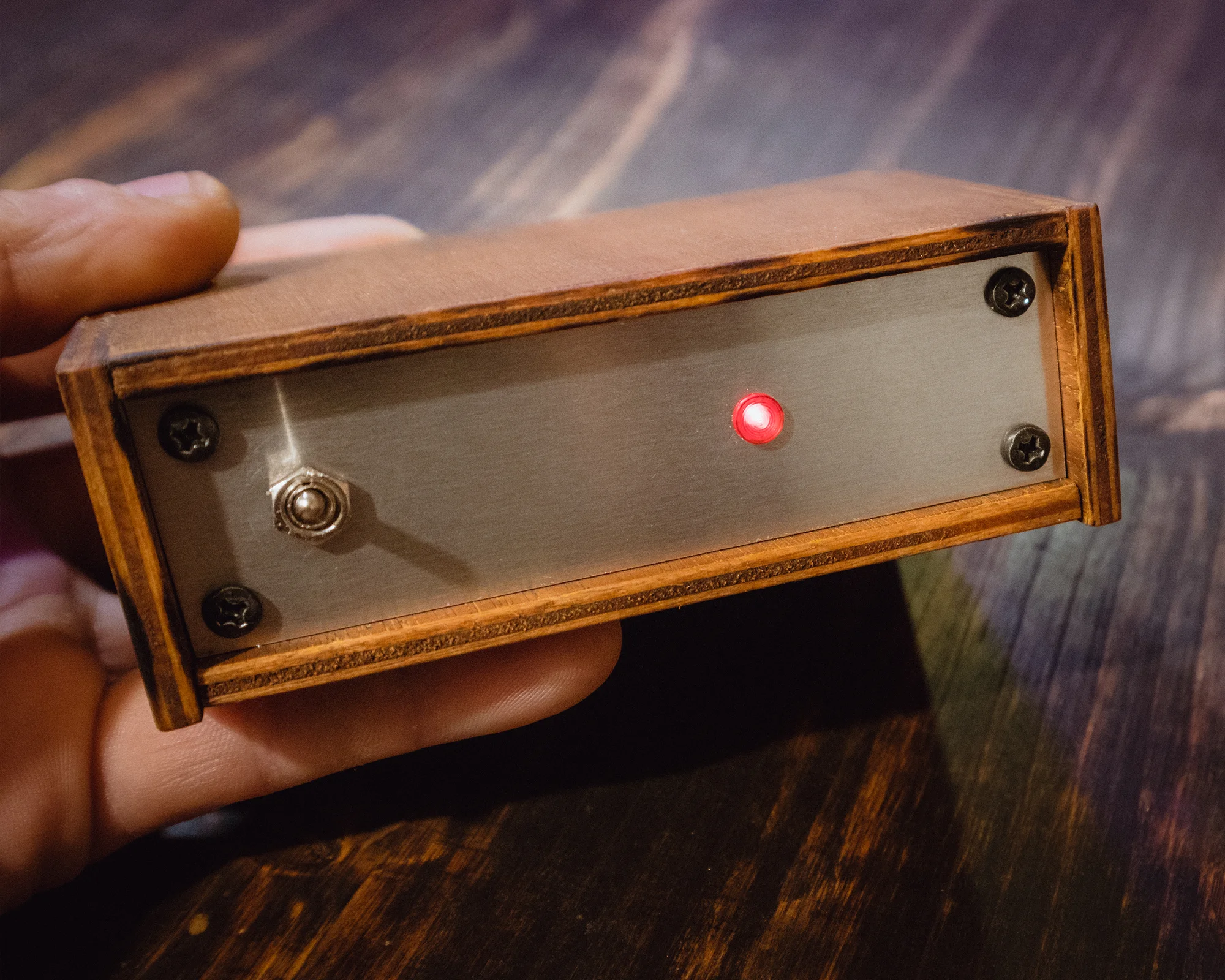
Pocket-Size VLF Up-Converter
Pocket-Size VLF Up-Converter Adjustments
Here are the only adjustment you have to make to this pocket-size VLF up-converter. Connect your converter to the antenna. Check the details from the video above for details on using EFHW antennas . Then connect your transceiver to the VLF up-converter using a coaxial cable. With the transceiver or receiver set on the 30m band ( 10MHz ), make sure you turn on the converter and you hear the tone generated around 10MHz. With the receiver or transceiver in CW more having the filter set as narrow as possible, tune the signal using the trimmer capacitor to exactly 10MHz. That’s it, now you are ready to explore the wonderful and fascinating world of VLF.
Here you have a video with more details on the construction of the VLF up-converter circuit board. This is the Manhattan style version I built for testing the circuit before designing the PCB board. This is the reason I didn’t repeated the information in the newer video above.
VLF Low Pass Filter
Here are a few notes of the low pass filter I used for this VLF up-converter. The impedance I used to calculate the filter it’s 1.5K both for the input and the output. The reason behind it it’s that the input of the NE612 it’s 1.5K. Since I had good results even when using a 50 Ohm antenna, I am happy with the way it performs. Clearly I will want to experiment a little more when it comes to antenna and various impedances of the antennas I am connection to the up-converter.
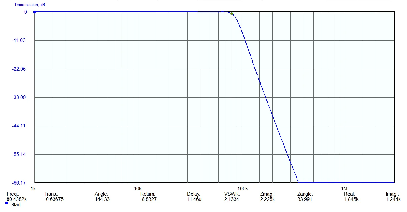
VLF Low Pass Filter Simulation
Why A VLF Up-Converter ?
Building a VLF up-converter for me was a much simpler solution than building a dedicated VLF receiver. I already had receivers and transceivers able to receive the 30m band. Having a pocket-size VLF up-converter also helps me to use it a lot easier when portable.
The SAQ Grimeton 2025 Christmas transmission on December 25th. I had a weak signal due to my poor antenna setup and location, but I did heard it. Clearly for the next transmission I will be more prepared.
Rewards For The Efforts
After all the effort you spend to build antennas for VLF and various receivers or up-converters like the one in this article, there are always ways to get your rewards Here is my e-QSL card from SAQ.
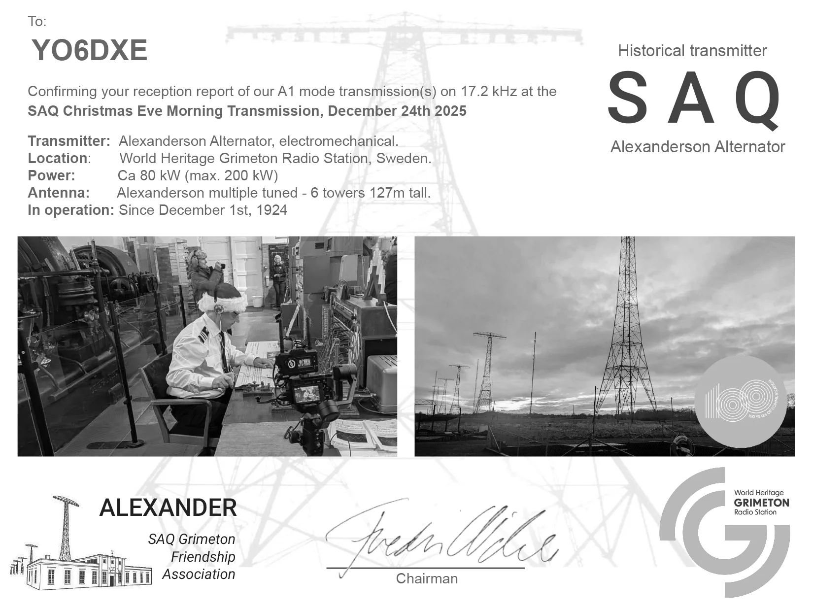
SAQ Grimeton e-QSL – YO6DXE
VLF Broadcasts
There are a lot of interesting VLF broadcasts that you can listen to. Many of them are military and submarine communications that clearly are encoded messages. You can still decode the digital transmissions using various amateur radio programs, but I doubt you will also decipher them. On this website you can find a list with the stations that broadcast between 10kHz and 150kHz.
The most important one that I am excited to receive it’s the Grimeton SAQ transmitter. Alexander Grimeton Friendship Association it’s a non-profit organization founded in 1996. The association’s purpose is to preserve, document and display the unique Alexanderson alternator at the old radio station in Grimeton, Sweden. This transmitter only transmits occasionally for special events. That is also the reason I am excited to receive this one. The frequency of the SAQ transmitter is 17.2kHz and you an receive it this year on 24th of December for the special Christmas transmission.
I am new to the world of VLF and initially for this Christmas transmission I was planning on building a VLF receiver. Due to the lack of free time and since this pocket-size VLF up-converter was so much easier to built I picked this one instead. So I hope I posted this article on time so you can build this project in time for the SAQ transmission. Good luck with the project and I hope you will get your QSL card this year from the Alexander Grimeton Friendship Association.
73, YO6DXE.