

Do you enjoy the content ? DONATE with PayPal to support me !
Get $5 of NEW USER FREE CREDIT using PCBWay. Full feature custom PCB prototype services, PCB assembly, SMD stencils, CNC / 3D Printing.
Introduction
FM Spy BUG with one transistor. It covers a distance between a few meters to a hundred meters using a single 2N3904. This Spy Bug was featured in an article on hackster.io ( thanks Gareth ). Please keep in mind that is made simply to learn and experiment. Is illegal to transmit on the public FM band on long distances so keep the transmitting distance to a minimum. It can also double as a baby monitor. Stay out of trouble !
This was a circuit built on many requests sent by the YouTube subscribers. Many tried the circuit but it didn’t work. In the video I explained a few possible reasons on why it doesn’t always works. Keep in mind that it’s not extremely stable in frequency, it was purely made for fun. It does work surprisingly well, way better than I expected. I do hope you will have fun with this project.
The Schematic
There are many schematics available online. The one I used was sent to me by a subscriber and I only made minor modifications to get it to work properly. This is just a simple version using only a few components. For those that are looking for something more powerful and possibly more stable in frequency, there are schematics using more transistors. Since I built this one just for fun and educational purposes, I kept it as simple as possible. All you have here it’s a simple oscillator with one 2N3904. The nice part is that as simple as it is, it’s really sensitive in picking up sounds.
This FM Spy BUG utilizes minimum power to transmit audio signals, unlike other more powerful FM transmitters. For the antenna I used a thin insulated flexible wire of about 20cm long. A small electret microphone it’s used to pick up the sounds. There is no microphone preamplifier in this circuit, but if you build it, you will realize that there is no need for one. In most schematics I also noticed the use of a trimmer capacitor. I realized that it was helpful to tune the transmitter on a particular frequency, but useless from many points of view so I decided not to use one.
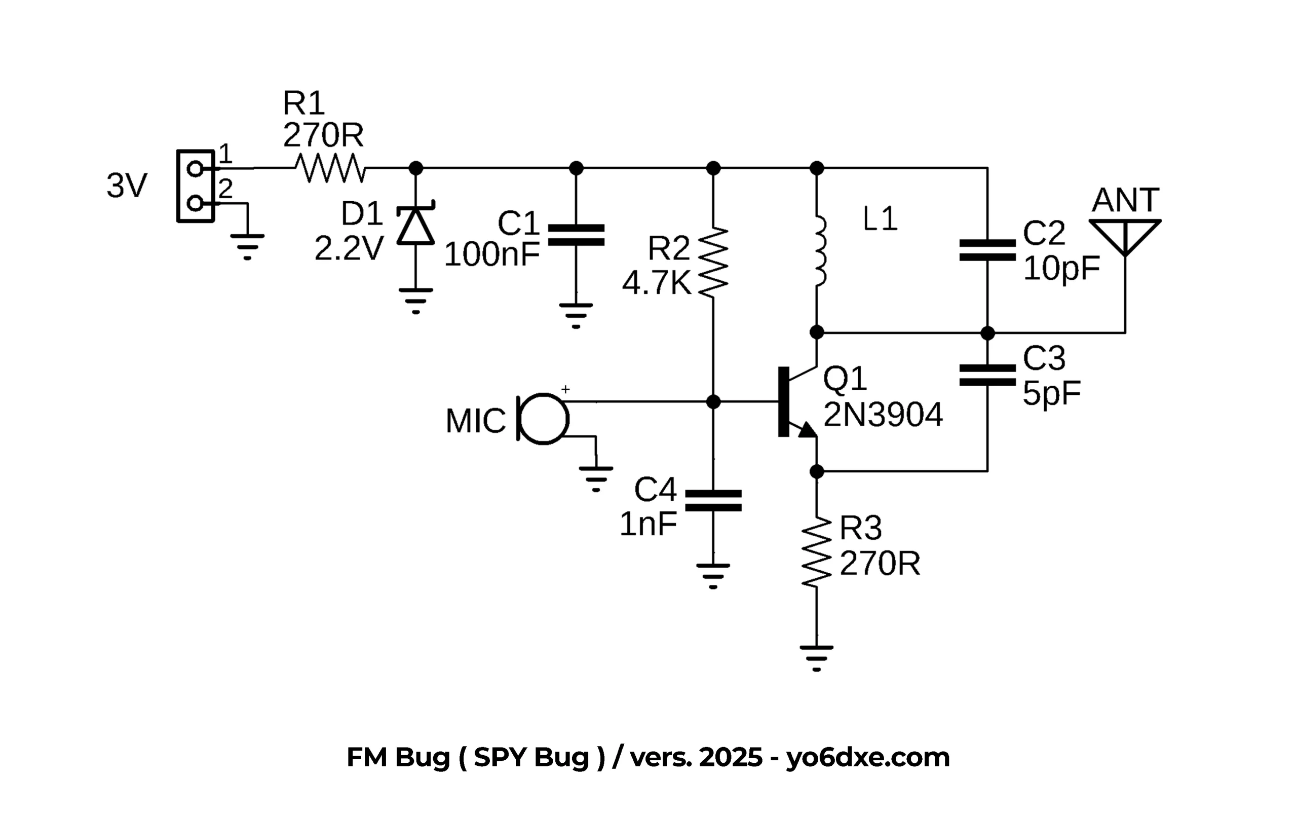
FM Spy BUG Schematic
Building The Spy BUG
The first time I tried it was on a breadboard so I can replace components really easy. When I was happy, I build the prototype you see in the image down bellow. The issues you have when building something so simple, it’s that nearly everything will change the transmit frequency. That was the reason I decided not to use the trimmer capacitor for frequency adjustment.
I calculated the tank circuit in a way that it would be easy to adjust the frequency only by playing with the spacing between the turns of the inductor L1. It should cover the top portion of the FM broadcast band and you should be able to tune it from around 98MHz up to 107MHz. Of course it all depends on the transistor and the inductance of L1. If you watch the video I explained how every little change can affect the transmit frequency. So one thing it’s that you may need some patience until you get it to work properly on the desired frequency.

FM Spy BUG Prototype
L1 it’s probably the most important part of the circuit together with the transistor. Using other transistors I had really strange results and the transmitter was on any other frequency but the one I needed it to be. Even by changing the inductor and the value of the capacitors didn’t helped much. To build L1 I used a 3mm diameter bamboo BBQ stick. You just have to wind 8 turns of 0.4mm enameled copper on the BBQ stick. In most cases this allowed me to tune the transmitter on the frequencies I mentioned earlier above. In some cases you may have to make adjustments and remove one turn or add another one.
Remember it’s a simple circuit so you may need to make a few adjustments. Also if you order the assembled version from PCB Way, you will still have to make these adjustments. If you want to increase the range you can use a longer antenna. A 1/4 element on 105MHz it’s about 68cm so you get an idea. I was more than happy with just 20cm. If you don’t have a tinySA, it will be a little harder to tune it, but with patience you will get it to work no worries.
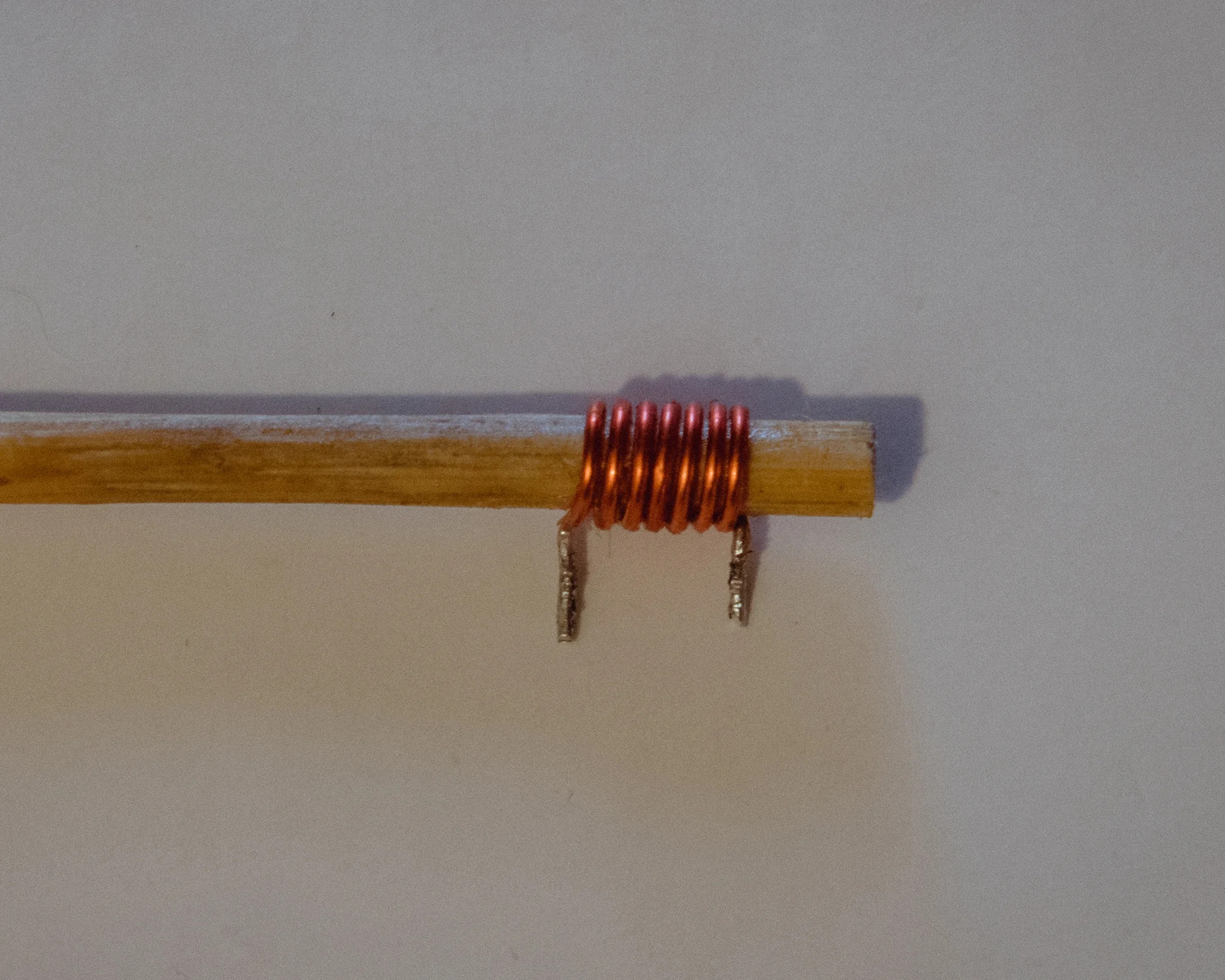
FM Spy Bug Inductor
The PCB Board
To make it easier for anyone to replicate the project, I designed a tiny PCB board that you can order from PCB Way. If you have the patience to make the PCB board using the toner transfer method, you have a PDF file for that in the download folder. I had enough of toner transfer so I simply prefer to use the PCB boards from PCB way. It looks way better too to be honest.

FM Spy BUG PCB Board
The Final Version
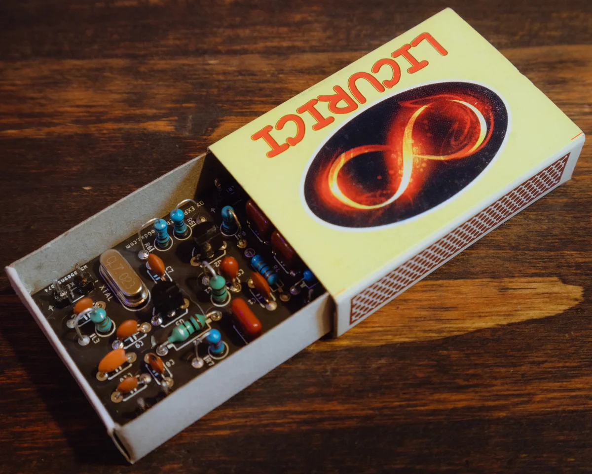
Here you have the final version of my Spy BUG. It’s small enough that it could fit in a thicker marker ( sharpie ). The idea was to use it inside a lamp as a baby monitor so keeping it extremely small didn’t make any sense. Now I power it with a 3.7V rechargeable battery that I had in my junk box, together with a USB charging circuit. It works like a charm and it takes some time until the voltage of the battery drops under 3V of the Zenner diode I am using ( I didn’t had a 2.2V Zenner diode ). I have to admit that I really like how it turned out. Be inventive and see what enclosures you can fit it into. But I will repeat myself, do not get in trouble.

One Transistor FM Spy BUG
A fun story and this may give you an idea on what you could use it for. This summer I had some thieves that used to come regularly to the houses nearby ( in construction ). They used to come for the materials they could get really easy with ought having to pay. So I really wanted to call the police but since they were coming late at night, I could not hear them. I left the microphone outside in the grass close to the houses hidden in a PVC pipe. Inside I had my FM receiver on and listening while sleeping. Trust me when you hear something strange you wake up… and I did. You can already guess the rest of the story. I have to admit that it was a pleasure to see a police chase on the fields around me just like the ones you see in the movies.
Conclusion And Building Tips
Even if we only used a few components, the FM Spy BUG performs really nice. Of course with a few more components we could make it easier to tune, more stable in frequency, etc. But then we lose all the fun of building something extremely simple. Now here is what you should know about the external factors that influence the frequency change. The place where you keep the FM Bug will influence the TX frequency. It depends of what you have around it.
The length of the antenna will also change the TX frequency. The voltage you are powering with will have the same effect. That was the reason I used the Zenner diode, as a simple voltage stabilizer. I wouldn’t go higher than 3.5V as I noticed that the microphone becomes way too sensitive and the audio you receive in the radio will be distorted. So with these in mind, you may have some more options when it comes to adjust the frequency of the transmitter. I hope you like it and if you built it, I hope it worked. Enjoy it and have fun with it, I sure did trust me.
73, YO6DXE.

Thanks my friend.
Always a pleasure buddy.
73, YO6DXE.