
Do you enjoy the content ? DONATE with PayPal to support me !
Get $5 of NEW USER FREE CREDIT using PCBWay. Full feature custom PCB prototype services, PCB assembly, SMD stencils, CNC / 3D Printing.
Introduction
This LC passive CW audio filter it’s not perfect by any means, but I found it very easy to build. It can be used before the input of any external audio amplifier ( as an active filter ). If the receiver or transceiver to which we want to add the CW filter has a slightly stronger audio output, we can listen quietly in headphones directly from the filter output. No need for an external audio amplifier after the filter. The best part is that it only needs a few components.
A version of this article was also published in the RADIO Magazine ( No. 5-6 June/July 2024 ), available in digital format translated in English downloadable as a PDF file.
The idea for this filter originates from an article written by KI3U. I experimented a little bit with the design using whatever I had on hand, until I was happy with the results.
The Schematic
After building all sorts of simple receivers and transceivers, I decided it would be useful to build an audio amplifier to be able to listen into an external speaker. Those projects only had the optimal audio output level for headphones. So I thought of also using an LC filter between the output of the audio amplifier and the headphones. The intention was to use it as a passive CW audio filter. Here is the schematic by KI3U that I started with.
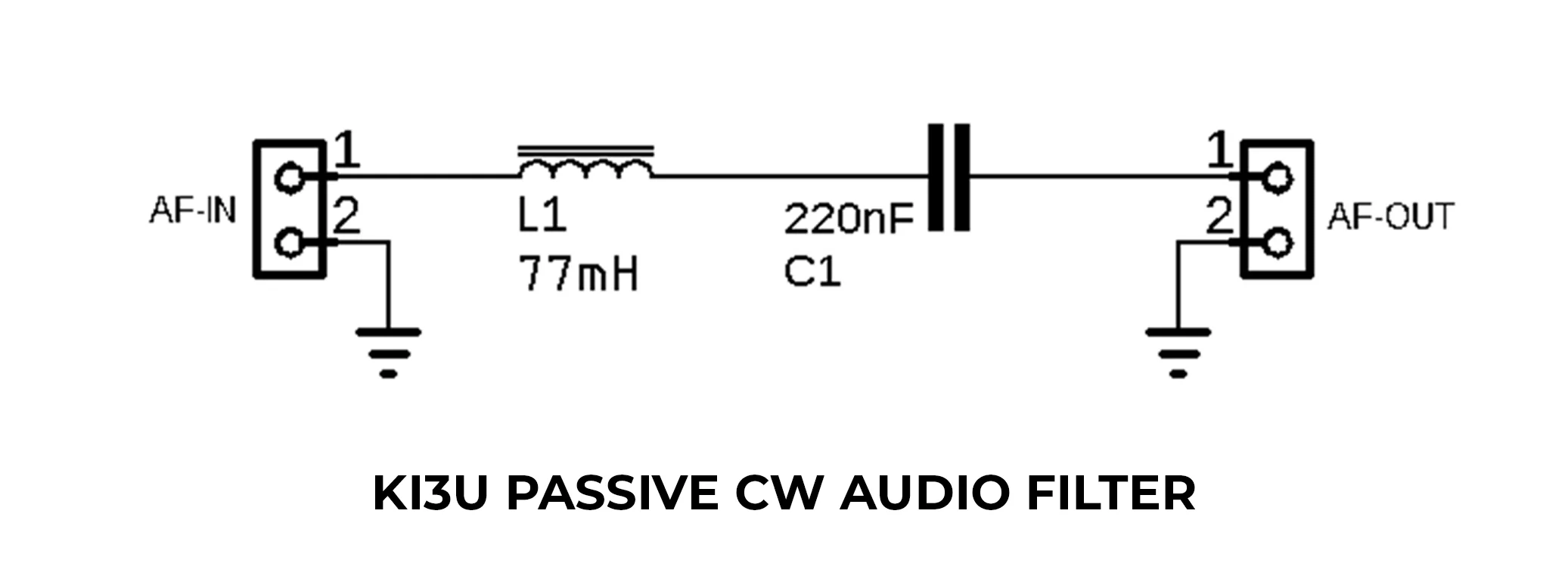
KI3U Passive CW Audio Filter
I decided to build and test the filter as shown above, but I didn’t like it because the audio level after the filter was quite low. I tried to find a way to install it between the audio output of the receiver and an audio amplifier. That way I could use it as an active CW audio filter, or rather an audio amplifier that includes a CW audio filter. In the image bellow you have the schematic for the filter modified to be used both as a passive filter, or as an active filter if placed before the audio amplifier. It can resonate either on 600Hz or 800Hz according to your preference.

Passive CW Audio Filter Schematic
Filter Simulation
I’m not much into computer circuit simulations, but for this filter I did a simulation to get an idea of what values I should use for the inductor and capacitors. Initially I made it only for 600Hz, but then I added the 800Hz option. Of course in reality the filter does not resonate exactly at 600Hz, but somewhere at 620Hz. It is quite close though, so I am super satisfied with the result. With the help of the 5K potentiometer, I can also adjust the bandwidth of the filter to my liking.
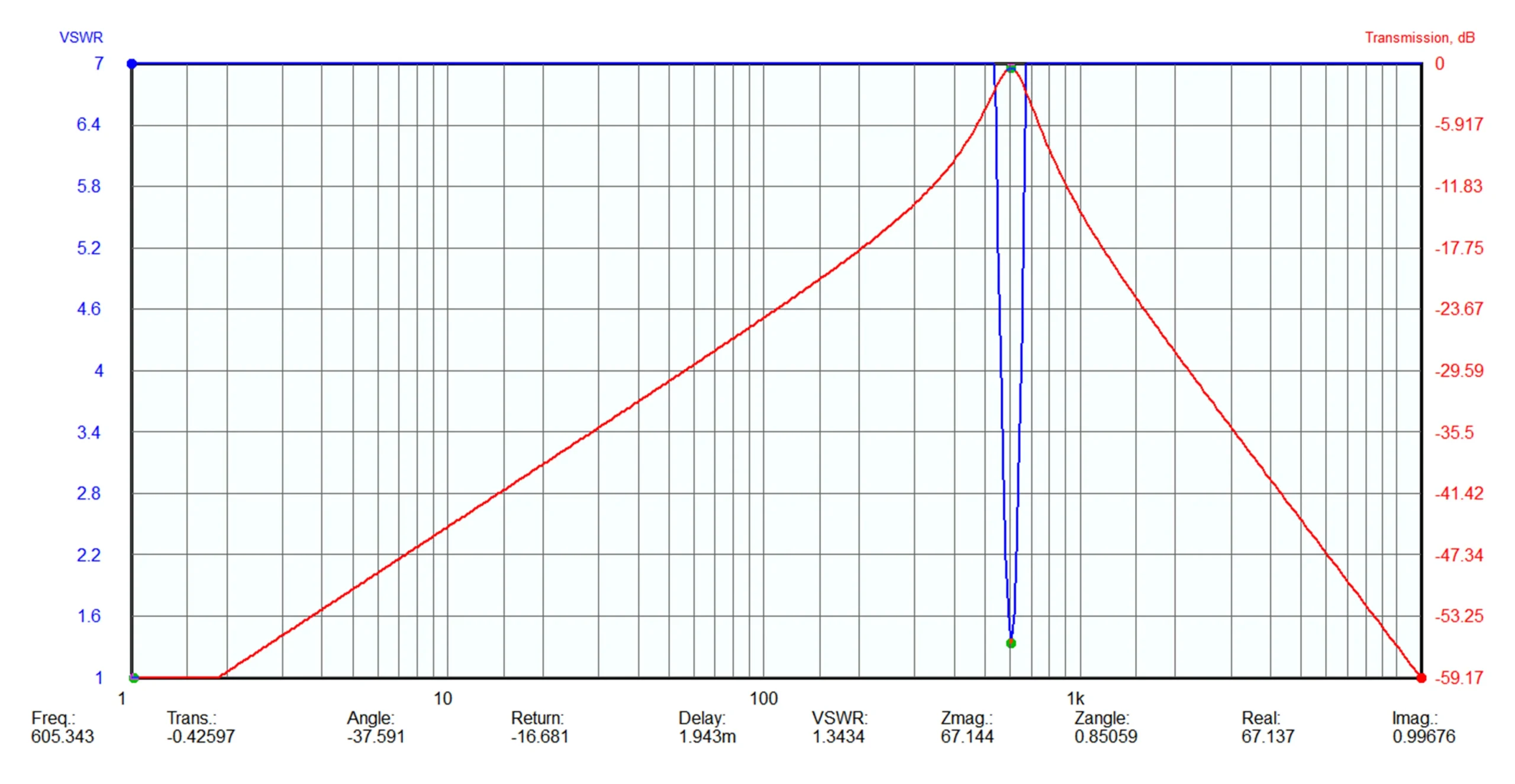
Passive CW Audio Filter Simulation
Building The Filter
My first problem was the lack of a proper inductor. I needed a reasonably large inductor with a Q as good possible. I tried all kinds of inductors that I had on hand, but the results did not satisfy me. I even tested the primary of some transformers used as an inductor, but the bandwidth in all cases was much too large. I decided to build an inductor myself with what I had on hand. I found a magnetic core of a DC filter recovered from a computer source. I don’t know exactly what type of magnetic material it is made of, nor the product code from the manufacturer. The center of the magnetic core was 18mm in diameter, so I made a cardboard case that I could wind on. I used 550 turns of 0.2mm CuEm. Initially I wound more turns and gradually decreased until I reached 160mH. I tested other values, but with 160mH I was the most satisfied.
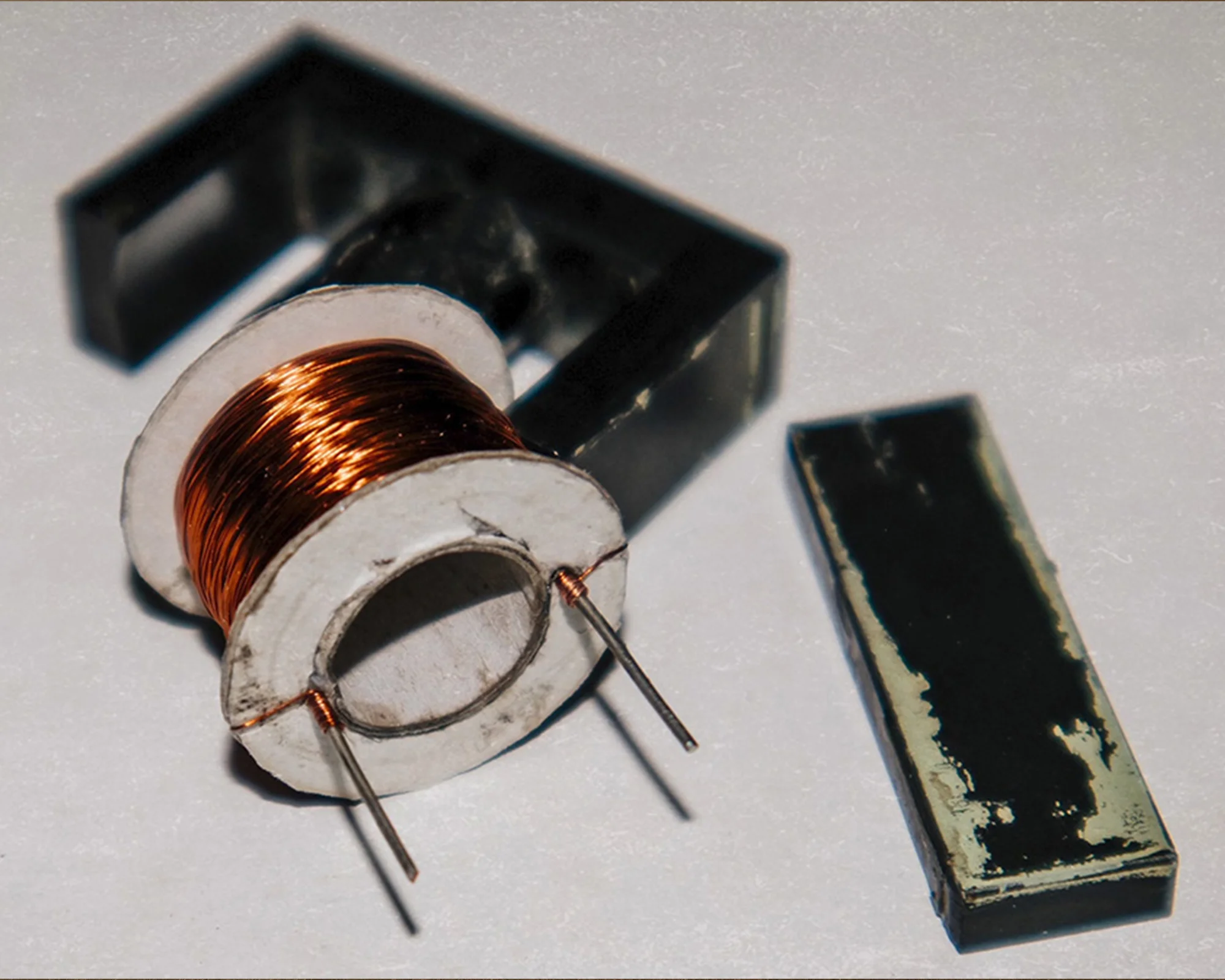
Homebrew 160mH Inductor
I then selected the capacitors needed for the filter. And here I tested different values until I got the desired results. You can test other values, but I wanted a filter with a narrow bandwidth, since I can adjust the bandwidth later with the potentiometer anyway. I used Mylar capacitors because I got the best results. I don’t know why, but in audio circuits they seem to have much better results compared to a ceramic capacitor of the same value. Since the filter was only for initial testing, I didn’t put it in a case, but built something simple out of double-layer PCB board.
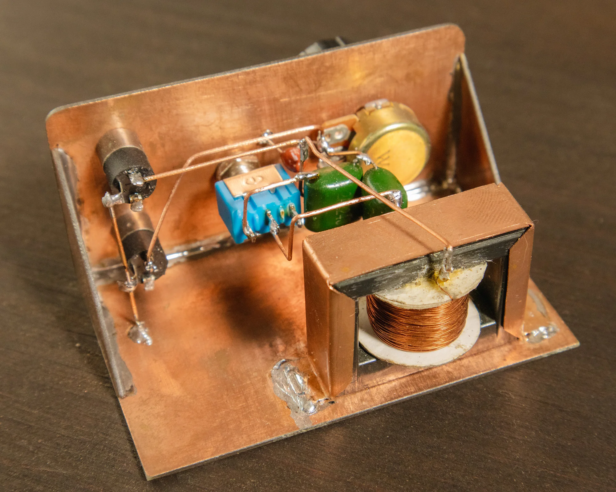
Passive CW Filter Construction Details
I also added a switch as shown in the schematic, to be able to select the resonance frequency of the filter at either 600Hz or 800Hz. I did this because in previous tests I found that very often this option can be useful. As for the audio amplifier, I made a very simple one with LM386. Basically the filter is mounted between the audio output of a receiver / transceiver and the external audio amplifier. I was pleasantly surprised by how narrow the bandwidth of the filter is. Often it can be too narrow ( it’s ringing ), so I have to adjust the bandwidth with the potentiometer.
However the result was adequate and it almost completely eliminates any interference. Especially those from the AM broadcast stations that always appear on very simple transceivers like the Pixie for example. The only disadvantage is the fixed frequency of the filter, at 600Hz or 800Hz. It would also be an option to make an inductor with several outputs of different values together with a rotary switch with the required number of positions. This way we could create a filter that would have different resonance frequencies ( I don’t think I would bother to do this ).
Adjustments And Testing
At the time I built the filter, I had no measuring device to find out the resonance frequency of the filter, so I became inventive. I installed an application on the phone that generates an audio tone at the frequency chosen by me ( preferably sinewave ). Here I leave it to you to choose, because there are many such applications. I connect the phone to the input of the audio filter, and the output of the filter to the audio amplifier. Now it depends how you prefer to use the filter in the future: either by listening in headphones or into a speaker. To find out where the filter resonates, we start the tone generator and change the frequency in the application between 100Hz and 1500-2000Hz. It is very easy to notice “by ear” the frequency at which the filter resonates. Small adjustments can eventually be made until the filter resonates at the desired frequency.
You can change the value of the inductor, but this is more difficult, so the easiest is to change the value of the capacitor used ( C1 and C2 in the schematic ). This is the only adjustment needed. Once brought to the desired resonant frequency, the filter is ready. I mentioned earlier that it is important if you choose the headphones or the speaker, because when we make the adjustments it is good to make them using the preferred option. A pair of headphones resonates differently at a certain frequency than a speaker. If you choose the speaker, it is recommended that it is already mounted in its box for optimal adjustment. C3 and the inductor change both the resonant frequency of the filter and the bandwidth. Smaller values mean larger bandwidth, and larger values mean narrower bandwidth. As a frequency, lower values mean a higher resonant frequency, and higher values lower the resonant frequency of the filter.
Final Thoughts
A very simple filter that doesn’t take much time to make, but with impressive results compared to its simplicity. I haven’t had much time for amateur radio lately, but when I do have some free time and learn the Morse code by listening to QSOs, the filter helps immensely especially when the conditions aren’t too great. I highly recommend this filter, especially since so far it seems to offer the best results compared to other transistor-based active filters I’ve tested. Of course, it does not compare with a specially made filter with dedicated integrated circuits, which is much more efficient. I for one chose it because of its simplicity and for the sake of using something more “vintage”. I hope it will be useful to you if you need a quick and easy CW filter.
73, YO6DXE